D-y7bal direct mounting style, D-y7bal, Caution – SMC Networks Reed Switch Solid State Switches User Manual
Page 24: Dimensions, Auto switch specifications, Weight, Grommet, Precautions
Auto Switch Internal Circuit
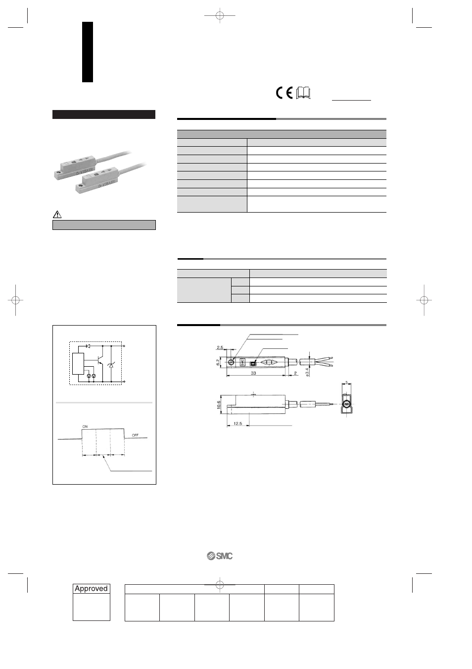
Dimensions
Grommet
Auto switch model
0.5
3
5
D-Y7BA
—
54
88
Lead wire length
(m)
Water (coolant) resistant type
Please consult with SMC if using coolant liquid
other than water based solution.
Indicator light/Display method
D-Y7BAL (With indicator light)
Auto switch model
Wiring type
Applicable load
Load voltage
Load current
Internal voltage drop
Leakage current
Indicator light
D-Y7BAL
2-wire
24 VDC Relay, PLC
24 VDC (10 to 28 VDC)
5 to 40 mA or less
4 V or less
0.8 mA or less at 24 VDC
Operating position······Red LED lights when ON.
Optimum operating position······Green LED lights when ON.
• Lead wire — Oil resistant, flexible vinyl heavy-duty cord, ø3.4, 0.15 mm
2
, 2 cores (Brown, Blue), 3 m
(Standard)
Note 1) Regarding the common specifications of the solid state switches, refer to page 12-13-5.
Note 2) Regarding the lead wire length, refer to page 12-13-5.
Auto Switch Specifications
PLC: Abbreviation of Programmable Logic Controller
Weight
(g)
Precautions
Operating range
Indication
Green
Red
Red
Optimum operating position
Water Resistant 2-color Indication Type
Solid State Switch: Direct Mounting Style
D-Y7BAL
Main circuit
of switch
OUT (
+
)
Brown
OUT (–)
Blue
Mounting screw M2.5 x 4
l
Slotted set screw
Indicator light
Most sensitive position
Caution
For details about certified products
conforming to international standards,
visit us at www.smcworld.com.
12-13-24
1st
12_13_D-.qxd 04.7.6 18:02 Page 13-24
24