Water resistant 2-color indication type, D-f7ba(v)l rail mounting style, D-f7ba(v)l – SMC Networks Reed Switch Solid State Switches User Manual
Page 22: Caution, Dimensions, Auto switch specifications, Weight, Grommet, Precautions
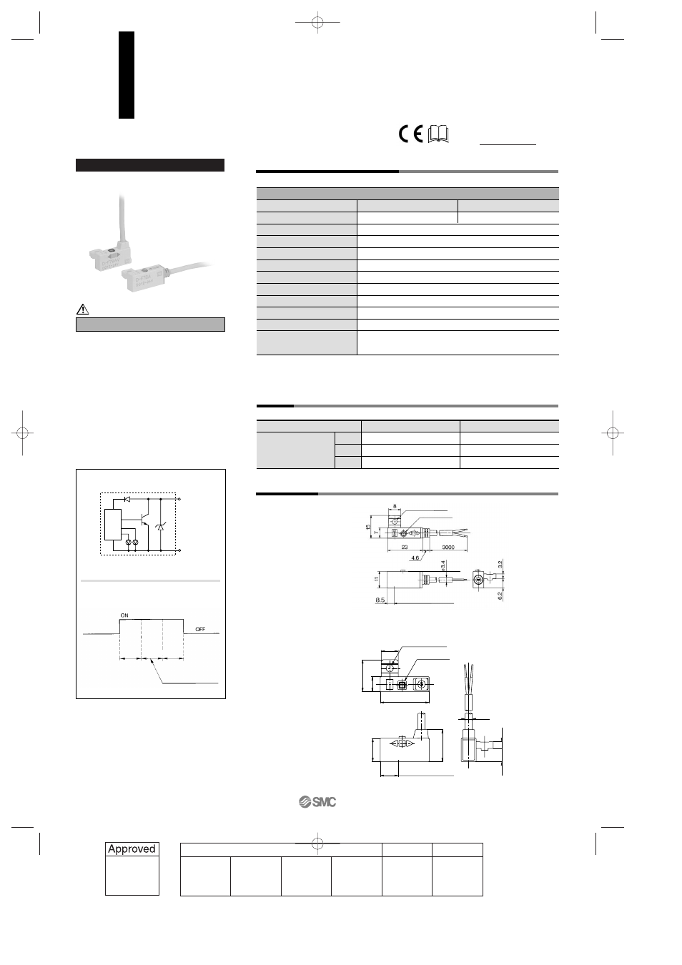
Auto Switch Internal Circuit
Dimensions
Grommet
Water (coolant) resistant type
Please consult with SMC if using coolant liquid
other than water based solution.
Indicator light/Display method
D-F7BA(V)L (With indicator light)
Auto switch model
Electrical entry direction
Wiring type
Output type
Applicable load
Power supply voltage
Current consumption
Load voltage
Load current
Internal voltage drop
Leakage current
Indicator light
D-F7BAL
2-wire
—
24 VDC Relay, PLC
—
—
24 VDC (10 to 28 VDC)
5 to 40 mA
4 V or less
0.8 mA or less at 24 VDC
Operating position······Red LED lights when ON.
Optimum operating position······Green LED lights when ON.
D-F7BAVL
Perpendicular
8.5
15
6.2
3.2
11
23
SMC
8
15
7
15
ø3.4
D-F7BAL
D-F7BAVL
Auto switch model
0.5
3
5
D-F7BA
—
50
81
D-F7BAV
—
50
81
Lead wire length
(m)
In-line
• Lead wire — Oil resistant vinyl heavy-duty cord, ø3.4, 0.2 mm
2
, 2 cores (Brown, Blue), 3 m (Standard)
Note 1) Regarding the common specifications of the solid state switches, refer to page 12-13-5.
Note 2) Regarding the lead wire length, refer to page 12-13-5.
Auto Switch Specifications
PLC: Abbreviation of Programmable Logic Controller
Weight
(g)
ø3.2 mounting hole
Most sensitive position
Indicator light
ø3.2 mounting hole
Most sensitive position
Indicator light
Precautions
Operating range
Indication
Green
Red
Red
Optimum operating position
Water Resistant 2-color Indication Type
Solid State Switch: Rail Mounting Style
D-F7BA(V)L
Main circuit
of switch
Caution
OUT (
+
)
Brown
OUT (–)
Blue
For details about certified products
conforming to international standards,
visit us at www.smcworld.com.
12-13-22
1st
12_13_D-.qxd 04.7.6 18:02 Page 13-22
22