How to overlap the projection images – Sanyo PLC HF15000L User Manual
Page 71
71
✔
Note:
• The overlapping area might become uneven depending on the images. In such a case, it is recommended to
decrease the contrast of the images in the Image Adjust Menu.
If the colors of the left and right images do not match, then follow the next step.
Select Color matching in the setting menu and display the Color matching dialog box.
Then, set Color matching to On and adjust the color settings (Red/Green/Blue).
(Refer to pages 57, 58 for operation procedure.)
6
Color matching
✔
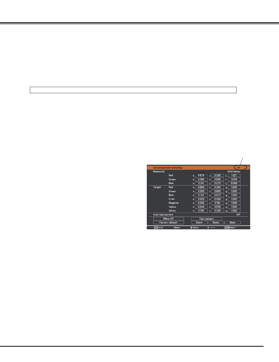
Note:
• When you change the values of Target, make sure that each
Target value should be within the range of Measured value.
(e.g., In the case of the Fig.1, the X value of Target-Red
should be within 0.674 which is the X value of Measured-
Red.)
Set to On.
5
Set Test pattern to On to display a 50 % white image. The overlap area will be brighter than the non-overlapping area.
Adjust the Black level in the Edge blending dialog box to increase the brightness of the non-overlapping area so that
the unevenness is reduced.
Select Advanced color matching if you need further adjustment.
In the Advanced color matching dialog box, set Advanced color matching to On and adjust the values of Target (Red/Green/
Blue/ Cyan/ Magenta/ Yellow/ White).
7
If color unevenness is still detected between the left image
and right image, measure chromaticity coordinates and
luminance of Red, Green, and Blue by using a colorimeter,
and then input the measured values by following the steps
below.
1. Ensure that the Advanced color matching function is set
to “On”.
2. Highlight “Test pattern” appearing at the lower part of the
window and press the SELECT button to display the Test
pattern window.
3. Select Red, Green, or Blue and press the SELECT button
to display the test pattern.
4. Measure chromaticity coordinates (X and Y) and
luminance (Lx) by using a colorimeter.
5. Highlight “Exit” in the Test pattern window and press the
SELECT button to return to the Advanced color matching
window.
6. Highlight the color of the coordinates and luminance that
you measured at the step 4, in the Measured section, and
press the SELECT button.
7. Input the measured chromaticity coordinates and
luminance values in the x and y fields.
8. The values to be input in the L fields can be calculated
according to the following formula:
L = Measured luminance of the color ÷ total measured
luminance of all colors (Red, Green, and Blue).
9. Readjust the Target values.
10. Highlight “Store” appearing at the lower part of the
Advanced color matching window and press the SELECT
button to store the values.
8
How to Overlap the Projection Images