2 installation, 1 panel pc 670 – Siemens PC 870 User Manual
Page 29
Mounting
3-3
SIMATIC Panel PC 670 / 870 Operating Unit, Equipment Manual
Edition 07/01
3.2
Installation
3.2.1
Panel PC 670
The operating unit can be fitted in the mounting cut-out with either
clamps or screws. Screwed joints are not possible with the 12.1”
touchscreen version!
Protection class IP 65 is possible when the operating unit is secured
with clamps (in conjunction with a continuous gasket).
Protection class IP 54 is achieved with screw fixings.
The permissible mounting locations will depend on the attached com-
puting unit.
Operating units
L1 L2 L3 L4 L5 A1 A2 S1 S2
(a) with key-based front panels:
10.4” TFT / 12.1” TFT
450 290
78 465 235 16
10
—
—
15.1” TFT
450 321
51 465 279 16
17
—
—
(b) with touchscreen front panels:
12.1” TFT
368 290 —
—
— 16
10
35
19
15.1” TFT
450 290 81 465 235 16
10
—
—
L1
L2
112
±
0.5
L4
L5
11
2
±
0.5
±
1
56
min. 1.5 – max. 6
L3
±
1
A1
±
1
A2
±
1
Clamp with grub screws
Drill hole for
±
0.2
±
0.2
+1
+1
Rz 120 (in gasket area)
Gasket area
M6/ 7
Pressure points
for clamps
screw fixings
L3
±
1
112
±
0.5
*)
*)
S1
±
1
S2
±
1
S1
±
1
S1
±
1
*)
cut-outs only for 15” TFT
(keyboard version),
(for dimensions,
see Fig. 3-1)
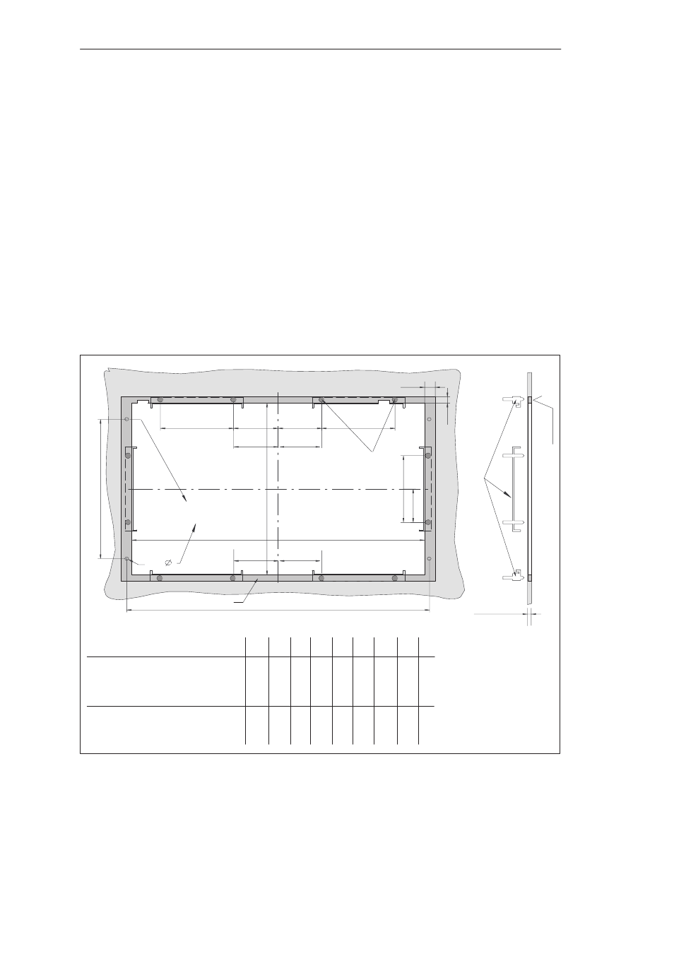
Fig. 3-3
Dimensions for installation of the operating unit of Panel PC 670
Mounting location
and dimensions