Datasheet – SMSC USB2640i User Manual
Page 25
Ultra Fast USB 2.0 Multi-Format Flash Media Controller/USB Hub Combo
SMSC USB2640/USB2641
25
Revision 2.0 (10-03-08)
DATASHEET
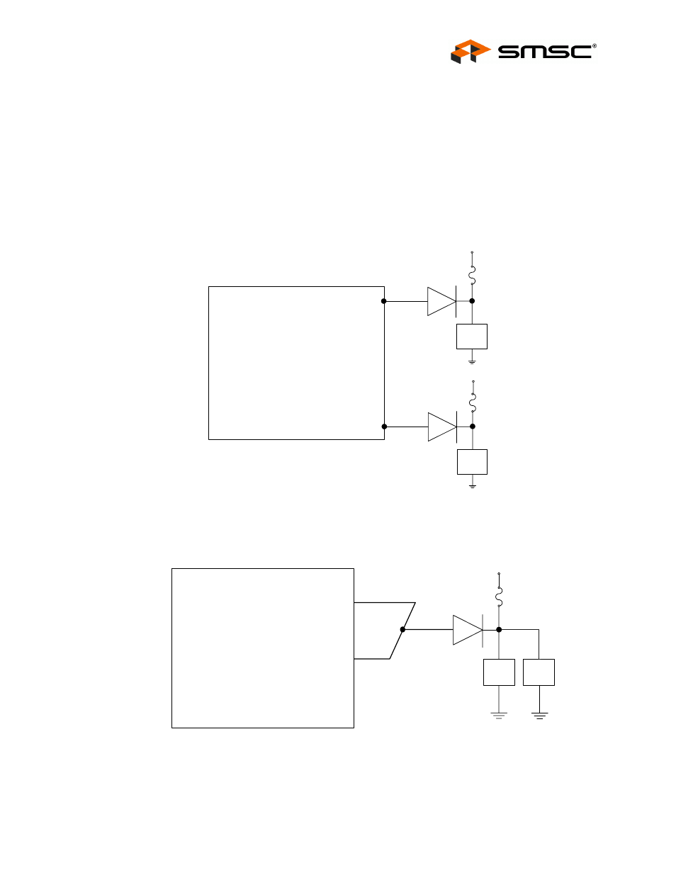
Port Power Control Using a Poly Fuse
When using the USB2640/USB2641 with a poly fuse, an external diode must be used (See Figure
6.2). When disabling port power, the driver will drive a '0'. This procedure will have no effect since the
external diode will isolate the pin from the load. When port power is enabled, the output driver is
disabled, and the pull-up resistor is enabled which creates an open drain output. This means that the
pull-up resistor is providing 3.3V to the anode of the diode. If there is an over-current situation, the
poly fuse will open. This will cause the cathode of the diode to go to 0V. The anode of the diode will
be at 0.7V, and the Schmitt trigger input will register this as a low resulting in an over-current detection.
The open drain output does not interfere.
Figure 6.2 Port Power Control with Single Poly Fuse and Multiple Loads
When using a single poly fuse to power all devices, note that for the ganged situation, all power control
pins must be tied together.
Figure 6.3 Port Power with Ganged Control with Poly Fuse
USB
Device
5V
PRTCTL3
USB
Device
5V
PRTCTL2
USB2640/
USB2641
USB
Device
Poly Fuse
5V
USB
Device
PRTCTL2
PRTCTL3
USB2640/
USB2641