4 capacitance, Table 9.1 pin capacitance, Capacitance – SMSC USB2640i User Manual
Page 57: Note 9.3, Note 9.4, Note 9.5, Note 9.6, Output vo, Datasheet
Ultra Fast USB 2.0 Multi-Format Flash Media Controller/USB Hub Combo
SMSC USB2640/USB2641
57
Revision 2.0 (10-03-08)
DATASHEET
Note 9.3
Output leakage is measured with the current pins in high impedance.
Note 9.4
See the USB 2.0 Specification, Chapter 7, for USB DC electrical characteristics
Note 9.5
RBIAS is a 3.3V tolerant analog pin.
Note 9.6
Output current range is controlled by program software. The software disables the FET
during short circuit condition.
Note 9.7
The 3.3V supply should be at least at 75% of its operating condition before the 1.8V supply
is allowed to ramp up.
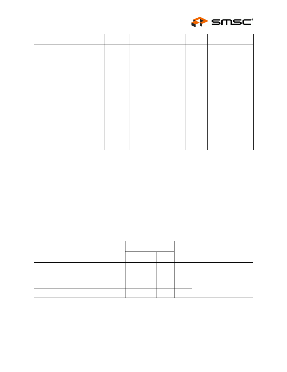
9.4
Capacitance
T
A
= 25°C; fc = 1 MHz; V
DD33
= 3.3V , V
DD18
= 1.8V
Integrated Power FET Set to 200
mA
Output Current (
Short Circuit Current Limit
On Resistance (
Output Voltage Rise Time
I
OUT
I
SC
R
DSON
t
DSON
200
181
2.1
800
mA
mA
Ω
μs
Vdrop
FET
= 0.46V
Vout
FET
= 0V
I
FET
= 70 mA
C
LOAD
= 10
μF
Supply Current Unconfigured
Hi-Speed Host
Full Speed Host
I
CCINTHS
I
CCINITFS
65
60
70
65
mA
mA
Supply Current Active
I
CC
280
300
mA
Supply Current Suspend
I
CSBY
420
550
µA
Supply Current Reset
I
RST
205
325
µA
Table 9.1 Pin Capacitance
PARAMETER
SYMBOL
LIMITS
UNIT
TEST CONDITION
MIN
TYP
MAX
Clock Input Capacitance
C
XTAL
2
pF
All pins (except USB pins
and pins under test) are tied
to AC ground.
Input Capacitance
C
IN
10
pF
Output Capacitance
C
OUT
20
pF
PARAMETER
SYMBOL
MIN
TYP
MAX
UNITS
COMMENTS