4 rom boot sequence, Figure 6.4 usb2640/usb2641 spi rom connection, Figure 6.5 usb2640/usb2641 i2c connection – SMSC USB2640i User Manual
Page 26: Rom boot sequence, Datasheet
Ultra Fast USB 2.0 Multi-Format Flash Media Controller/USB Hub Combo
Revision 2.0 (10-03-08)
26
SMSC USB2640/USB2641
DATASHEET
6.4
ROM BOOT Sequence
After power-on reset, the internal firmware checks for an external SPI flash device that contains a valid
signature of "2DFU" (device firmware upgrade) beginning at address 0xFFFA. If a valid signature is
found, then the external ROM is enabled and code execution begins at address 0x0000 in the external
SPI device. Otherwise, code execution continues from the internal ROM.
If there is no SPI ROM detected, the internal firmware then checks for the presence of an I
2
C ROM.
The firmware looks for the signature ‘ATA2’ at the offset of 0xFC-0xFF in the I
2
C ROM. The firmware
reads in the I
2
C ROM to configure the hardware and software internally. Please refer to section
EEPROM Data Descriptor on page 28
for the details of the configuration options.
The SPI ROM required for the USB2640/USB2641 must be 1 Mbit and support either 30 MHz or 60
MHz. The frequency used is set using the SPI_SPD_SEL. For 30 MHz operation, this pin must be
pulled to ground through a 100 k
Ω resistor. For 60 MHz operation, this pin must pulled up through a
100 k
Ω resistor. SPI_SPD_SEL: This pin is used to choose the speed of the SPI interface. During
nRESET assertion, this pin will be tri-stated with the weak pull-down resistor enabled. When nRESET
is negated, the value on the pin will be internally latched, and the pin will revert to SPI_DO functionality,
the internal pull-down will be disabled.
The firmware can determine the speed of operation on the SPI port by checking the SPI_SPEED in
the SPI_CTL register (0x2400 - RESET = 0x02). Both 1- and 2-bit SPI operation is supported. For
optimum throughput, a 2-bit SPI ROM is recommended. Both mode 0 and mode 3 SPI ROMS are also
supported.
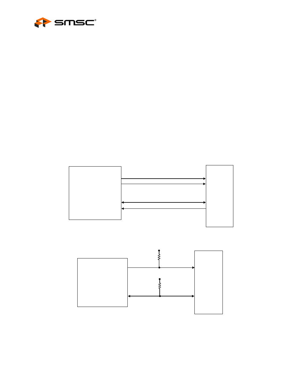
Figure 6.4 USB2640/USB2641 SPI ROM Connection
Figure 6.5 USB2640/USB2641 I
2
C Connection
SPI_CE_N
SPI_CLK / GPIO4 / SCL
SPI_DI
USB2640/
USB2641
SPI_DO / GPIO5 / SDA / SPI_SPD_SEL
SPI ROM
CE#
CLK
DO
DI
I
2
C ROM
SCL
SDA
3.3V
3.3V
10K
10K
USB2640/
USB2641