5 menu switch setting information – JVC BR-D95U User Manual
Page 69
136
13-4 Contents of the sense commands
13 RS-232C protocol
JVC Status (No. 4) Forth byte
Bit
Status
Remarks
Bit-7
TBC board
The TBC board is installed.
Always “1”
Bit-6
TC board
The TC board is installed.
Always “1”
Bit-5
DA3 Ins Lamp
Audio-3 Insert editing mode
is selected.
Bit-4
DA4 Ins Lamp
Audio-4 Insert editing mode
is selected.
Bit-3
Auto mode
Auto Edit/Preview/Review
being executed.
Bit-2
Unused
Always “0”
Bit-1
Unused
Always “0”
Bit-0
Unused
Always “0”
The bit assignment for status data each byte returned
with DD: JVC Status Sense is as follows:
JVC Status (No. 1) First byte
Bit
Status
Remarks
Bit-7
Undefined
Always “1”
Bit-6
Undefined
Always “0”
Bit-5
Unused
Always “0”
Bit-4
Unused
Always “0”
Bit-3
Unused
Always “0”
Bit-2
Unused
Always “0”
Bit-1
JVC Table 1
JVC Table-1 is selected.
Bit-0
Local
“Local” is selected.
JVC Status (No. 2) Second byte
Bit
Status
Remarks
Bit-7
Generator
The TC generator is selected
for the current timer mode.
Bit-6
UB
UB is selected for the current
timer mode.
Bit-5
TC
TC is selected for the current
timer mode.
Bit-4
CTL
CTL is selected for the
current timer mode.
Bit-3
CTL
CTL
Interpolation
Interpolation
Bit-2
DF
DF is selected for the current
timer mode.
Bit-1
LTC
LTC is selected for the
current timer mode.
Bit-0
Unused
Always “0”
JVC Status (No. 3) Third byte
Bit
Status
Remarks
Bit-7
REC Run
TC setting is 1: REC Run 0:
Free Run.
Bit-6
Regen
TC setting is 1: Regen 0:
Preset.
Bit-5
Ext
TC setting is 1: Ext 0: Int
Bit-4
TC Ins Lamp
TC Insert editing mode is
selected.
Bit-3
DA1 Ins Lamp
Audio-1 Insert editing mode
is selected.
Bit-2
DA2 Ins Lamp
Audio-2 Insert editing mode
is selected.
Bit-1
V Ins Lamp
Video Insert editing mode is
selected.
Bit-0
Assem Lamp
Assemble editing mode is
selected.
137
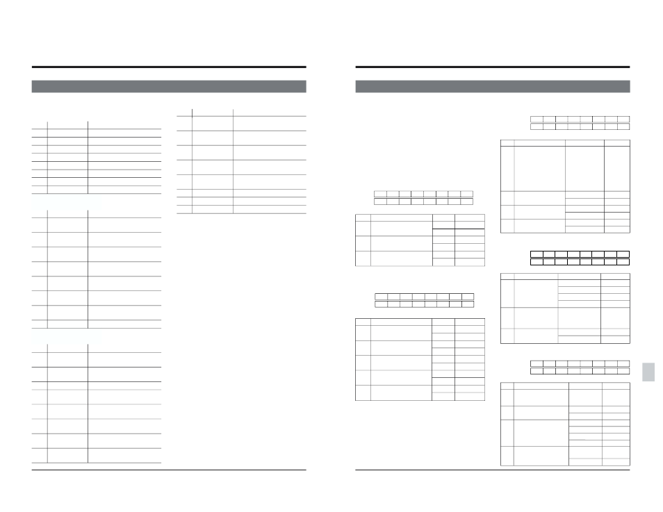
13-5 Menu switch setting information
13 RS-232C protocol
The set value expresses the corresponding bit value.
2 bits or more are expressed as follows:
0
0
1
1
2
10
3
11
4
100
5
101
:
:
SERVO information/SYSTEM information-1
DATA0 01
Corresponding menu switches
No.
Menu switch name
Setting
Set value
002
OPERATION LOCK
OFF
0
ON
1
003
SYNC SELECT
EXT
1
AUTO
3
005
AUTO TRACKING
OFF
0
ON
1
SYSTEM information-2
DATA0 08
Corresponding menu switches
No.
Menu switch name
Setting
Set value
D95
525/625
525
0
625
1
300
DIRECT EJECT
OFF
0
ON
1
301
DIRECT SEARCH
OFF
0
ON
1
302
BACK SPACE
OFF
0
ON
1
312
AUTO REW AT
OFF
0
TAPE END
ON
1
SYSTEM information-3
DATA0 10
Corresponding menu switches
No.
Menu switch name
Setting
Set value
307 PAUSE/STILL/STP
1 SEC
0
TIME
10 SEC
1
30 SEC
2
1 MIN
3
2 MIN
4
3 MIN
5
4 MIN
6
5 MIN
7
311 AUTO PLAY AT
OFF
0
TAPE BEGIN
ON
1
314 PB/EE MODE
STOP/FF/REW
0
STOP
1
328 EDIT POINT CLEAR
DISABLE
0
ENABLE
1
SYSTEM information-4
DATA0 20
Corresponding menu switches
No.
Menu switch name Setting
Set value
317 9PIN DEVICE ID
JVC D80
0
JVC D860/D92/D95
1
DVW-A500
2
USE SETTING (382–385)
3
320 PREROLL TIME
0SEC
0
:
:
15SEC
15
323 PREROLL END
STANDBY-ON
0
MODE
STILL
1
SYSTEM information-5
DATA0 40
Corresponding menu switches
No.
Menu switch name
Setting
Set value
390 SWAP VTR SELECT
AUTO
0
:
:
TYPE-9
9
391 SYNCRONIZATION
DISABLE
0
ENABLE
1
393 SYNC GRADE
ACCURATE
0
+/-1FRAME
1
+/-2FRAME
2
ROUGH
3
395 AUTO-EE
RECORDER
ONLY
0
AUTO-EE
1
7
6
5
4
3
2
1
0
D1
307 307 307
D2 328
311 314
7
6
5
4
3
2
1
0
D1 005
002
D2
003 003
7
6
5
4
3
2
1
0
D1
312
302 301 300
D2
D95
7
6
5
4
3
2
1
0
D1 317 317
D2
323
320 320
320
320
7
6
5
4
3
2
1
0
D1
391
395
D2 390 390 390 390
393 393