4 time code playback – JVC BR-D95U User Manual
Page 51
100
10-3 TIME CODE RECORDING
10 HOW TO USE TIME CODE
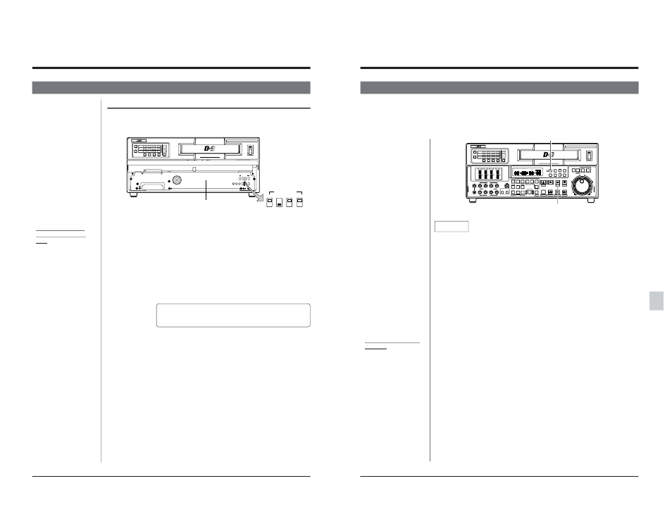
Front sub panel
Notes
● Drop/Non-drop Frame
mode selection (NTSC
only)
Automatically selected
according to the mode of
the received time code
(Drop Frame or Non-drop
Frame).
● Regeneration operation
• When time code is being
regenerated with input
time code, the built-in time
code generator stops
counting when no time
code is input.
● In the Play mode, time
code regeneration is based
on the playback time code
value.
● Inserting time code
If only time code data is
being inserted, record it on
the main time code. It is not
possible to insert it in the
sub time code.
1. Front sub panel switch setting
● Select the External Time Code Generator mode by setting the [INT/EXT]
switch to “EXT”.
The [FREE/REC] and [PRESET/REGEN] switch settings are not necessary.
● Select the Counter Display or On-screen Display mode to TC or UB with the
[COUNTER] and [SHIFT] buttons.
2. Menu switch setting
● Select the external time code to be regenerated.
● Menu switch No. 409
LTC (0): Regenerates the LTC time code input through the rear panel
[TC IN] connector.
Input LTC time code should be regenerated (matched in
terms of sync and phase) with video signals. Make sure you
input an external sync signal to the feeding equipment.
VITC (1): Regenerates the VITC time code superimposed on the video
signal input through the rear panel VIDEO IN connector.
● User bit data selection
● Menu switch No. 457
OFF (0):
User bits regenerated by the time code generator of this unit is
recorded.
ON (1):
The user bit auto preset function is activated and the user bit
data stored in the built-in memory is recorded.
● Select the sub time code.
● Menu switch No. 450 (Initial setting: ON(1))
OFF (0):
“00:00:00:00” is always recorded on the sub time code.
ON (1):
Records the input VITC time code in the sub time code.
3. Record the time code.
Press the [PLAY] button while pressing the [REC] button.
[
The selected time code will be recorded.
Recording the time code data output from the external time code generator
Externally generated time code can be recorded after being regenerated with the
time code data output from the built-in time code generator.
POWER
ON
I
OFF
O
CH1
AUDIO
INPUT
VIDEO
INPUT
AUDIO
MONITOR
VIDEO CASSETTE RECORDER
BR-D95U
CH2
CH3
CH4
CH1
CH2
CH3
CH4
CH1
CH2
CH3
CH4
SIF
SDI
AES/EBU
AUDIO INPUT / AUDIO MONITOR SELECT
LINE
CPN
L
ANALOG
R
SERVICE USE ONLY
TIME CDOE
INT
DF
FREE PRESET
EXT
NDF
REC
REGEN
Variable Motion
COMPONENT DIGITAL
OFF
RF
HID
GND
8
ON
ON
4
OFF
TIME CDOE
INT
FREE PRESET
EXT
DF
NDF
REC
REGEN
ON SCREEN
CF
(625)
101
10-4 TIME CODE PLAYBACK
10 HOW TO USE TIME CODE
Time code is output through the rear panel [TC OUT] and [VIDEO OUT] connectors during playback. VITC time
code with the time code data superimposed on the video signal is output through the [VIDEO OUT-LINE] connector.
Sub time code is output through the [VIDEO OUT-LINE] connector as VITC time code when menu switch No. 451
Setting
1. Front panel switch setting
● Select a Counter Display mode to TC or UB with the [COUNTER] and [SHIFT]
buttons.
2. Menu switch setting
● For VITC time code output, select a line to be added to the video signal.
● Menu switch No. 400
(Initial setting: NTSC 16 LINE/PAL 19 LINE)
● Menu switch No. 401
(Initial setting: NTSC 18 LINE/PAL 21 LINE )
● Select VITC time code output through the [VIDEO OUT] connector.
Menu switch No. 451
SUB TC (0)
: Outputs the VITC time code recorded in the sub time code.
TC (1)
: Outputs the time code recorded in the main time code.
OFF
: VITC time code is not output from the [VIDEO OUT]
connector.
Factory setting : TC (1)
● Select the Time Code Output mode during search.
Menu switch No. 452
OFF (0) : Outputs time code through the [TC OUT] connector during search
at X1.
ON (1) : Outputs time code through the [TC OUT] connector during search
at all speeds. Continuous time code is not available.
3. Play back the time code.
Press the [PLAY] button.
[
The selected time code is played back.
TCR or UBR is shown with the on-screen time code data.
● LTC time code is output from the [TC OUT] connector.
● Main or sub time code selected with menu switch No. 451 SELECT> is superimposed on video signals and output to the line selected ● On-screen display of sub time code Sub time code is displayed POWER ON I OFF O M H F S REC MENU PLAY PAUSE/STILL REW STOP FF EJECT PHONES CH1 CH2 CH3 CH4 REC PLAY PULL FOR VARIABLE TRACKING CH1 CH1 CH2 CH3 CH4/ TRACKING SET HOLD PB PB/EE COUNTER UB CONDITION AUDIO VIDEO AUDIO MONITOR PULL RESET VCON REMOTE TOP VIDEO AUDIO OTHERS ON SCREEN TIME CODE SERVO/SYS USER INSERT STAND BY PLAYER SEARCH VAR P.PLAY DA3 DA2 DA1 VIDEO ASSEM IN ENTRY OUT CANCEL SHIFT REVIEW METER MODE TRACKING FINE PREVIEW AUTO EDIT PREROLL TC RECORDER DA4 VIDEO CASSETTE RECORDER BR-D95U STILL X-1 REV FWD X1 CH2 CH3 CH4 CH1 CH2 CH3 CH4 CH1 CH2 CH3 CH4 SIF SDI AES/EBU AUDIO INPUT / AUDIO MONITOR SELECT LINE CPN L ANALOG R PULL RELEASE CTL P.READ AUTO OFF V.VAR REMOTE PB/EE 16:9 TC UB DF SERVO GEN CF AP 525 OVER –60 –2 –4 +2 +4 0 –40 –30 –20 –10 0 dB dB R P OVER –60 –2 –4 +2 +4 0 –40 –30 –20 –10 0 dB dB R P OVER –60 –2 –4 +2 +4 0 –40 –30 –20 –10 0 dB dB R P OVER –60 –2 –4 +2 +4 0 –40 –30 –20 –10 0 dB dB R P 625 Variable Motion COMPONENT DIGITAL [PLAY] button [COUNTER] button ● When you are using this deck as a player, the
with menu switch No. 400 and No. 401 from the [VIDEO OUT] connector.
with the main time code
when menu switch No. 451
is set to “SUB TC (0)”.
INPUT
INPUT
RELEASE
recording time code may
not be regenerated when
you output embedded
audio (SERIAL V/A OUT)
signals to the BR-D750U,
BR-D85U or BR-D80U. In
this case, set menu switch
No. 237