2 video signal system selection, 3 menu switch setting, Mh f s rec menu play pause/still rew stop ff eject – JVC BR-D95U User Manual
Page 16: Still x-1 rev fwd x1, Component digital, Menu, Reset vcon remote, Insert, Tracking fine, Video cassette recorder
30
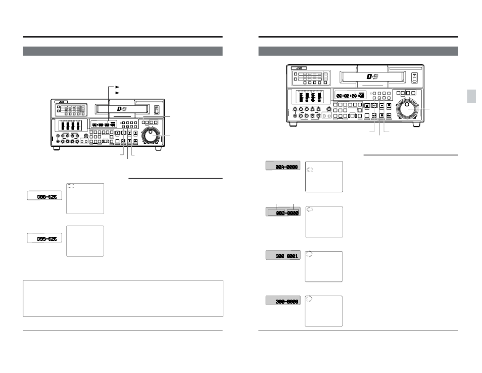
4-2 VIDEO SIGNAL SYSTEM SELECTION
This unit can be used with either the NTSC or PAL signal systems. The currently selected video signal system is
indicated by the 525/625 indicator on the counter display. To change the video signal system, follow the steps
below.
POWER
ON
I
OFF
O
M
H
F
S
REC
MENU
PLAY
PAUSE/STILL
REW
STOP
FF
EJECT
PHONES
CH1
CH2
CH3
CH4
REC
PLAY
PULL FOR VARIABLE
TRACKING
CH1
CH1
CH2
CH3
CH4/
TRACKING
SET
HOLD
PB
PB/EE
COUNTER
UB
CONDITION
AUDIO
INPUT
VIDEO
INPUT
AUDIO
MONITOR
PULL
RELEASE
RESET
VCON
REMOTE
TOP
VIDEO
AUDIO
OTHERS
ON SCREEN
TIME CODE
SERVO/SYS
USER
INSERT
STAND BY
PLAYER
SEARCH
VAR
P.PLAY
DA3
DA2
DA1
VIDEO
ASSEM
IN
ENTRY
OUT
CANCEL
SHIFT
REVIEW
METER MODE
TRACKING
FINE
PREVIEW
AUTO EDIT
PREROLL
TC
RECORDER
DA4
VIDEO CASSETTE RECORDER
BR-D95U
STILL
X-1
REV
FWD
X1
CH2
CH3
CH4
CH1
CH2
CH3
CH4
CH1
CH2
CH3
CH4
SIF
SDI
AES/EBU
AUDIO INPUT / AUDIO MONITOR SELECT
LINE
CPN
L
ANALOG
R
PULL
RELEASE
CTL
P.READ
AUTO OFF
V.VAR
REMOTE
PB/EE
16:9
TC UB DF SERVO
GEN
CF
AP
525
OVER
–60
–2
–4
+2
+4
0
–40
–30
–20
–10
0
dB
dB
R
P
OVER
–60
–2
–4
+2
+4
0
–40
–30
–20
–10
0
dB
dB
R
P
OVER
–60
–2
–4
+2
+4
0
–40
–30
–20
–10
0
dB
dB
R
P
OVER
–60
–2
–4
+2
+4
0
–40
–30
–20
–10
0
dB
dB
R
P
625
525
625
Variable Motion
COMPONENT DIGITAL
[HOLD] button
[SEARCH] button
[MENU] button
[SET] button
: NTSC
: PAL
Jog dial
4 MENU SWITCH SETTING
Operation procedure
1. Press the [MENU] button to display the top
menu.
2. Turn the jog dial to select “D95: 525/625”.
“D95” is shown on the counter display and “D95”
blinks on screen.
3. Hold the [SEARCH] button down and turn the
jog dial to select the set value.
Select “525” for NTSC or “625” for PAL.
4. To change the menu switch setting, hold the
[SET] button down and press the [HOLD]
button.
[
The Normal Display mode is restored.
5. To apply the selected video signal system, turn
this unit OFF then ON again.
[
When the power is turned ON, the video signal
system is changed and the corresponding
video signal system indicator is shown on the
counter display (525 or 625 indicator).
• When a cassette tape recorded on a signal system other than that set for this unit is played back, the
corresponding indicator ([525] or [625]) blinks.
When the NTSC system is selected and a PAL tape is played back, the [625] indicator blinks.
When the PAL system is selected and an NTSC tape is played back, the [525] indicator blinks.
• If required, select the audio reference level (-20 dB/-18 dB) for recording with menu switch No. 257 REF. SIGNAL LEV. >. (See page 54.) Video signal system indicator [Counter display] [On-screen display] D95:525/625 00A:MENU SETTING SET+HOLD INITIAL 00B:DIRECT ACCESS SET+HOLD>ON 00C:USER PAGE SET+HOLD>INITIAL 00D:MENU LOCK SET+HOLD>OFF M H F S SET+HOLD[POWER OFF>525 D95:525/625 00A:MENU SETTING SET+HOLD INITIAL 00B:DIRECT ACCESS SET+HOLD>ON 00C:USER PAGE SET+HOLD>INITIAL 00D:MENU LOCK SET+HOLD>OFF M H F S SET+HOLD[POWER OFF>525 31 D95:525/625 SET+HOLD[POWER OFF>525 00A:MENU SETTING SET+HOLD INITIAL 00B:DIRECT ACCESS SET+HOLD>ON 00C:USER PAGE SET+HOLD>INITIAL 00D:MENU LOCK SET+HOLD>OFF 002:OPERATION LOCK OFF 003:SYNC SELECT AUTO 005:AUTO TRACKING ON 300:DIRECT EJECT ON 301:DIRECT SEARCH ON 302:BACK SPACE ON 307:PAUSE/STILL/STP TIME 311:AUTO PLAY OFF 300:DIRECT EJECT OFF 301:DIRECT SEARCH ON 302:BACK SPACE ON 307:PAUSE/STILL/STP TIME 311:AUTO PLAY OFF M H F S M H F S M H F S M H F S 008:CAP LOCK(525) SW SEL 009:CAP RE-LOCKING DIR. ACCELERATION 5MIN 5MIN 4-3 MENU SWITCH SETTING 4 MENU SWITCH SETTING [Counter display] [On-screen display] Menu switch setting Top menu display Operation procedure 1. Call up the menu switch setting display. Press the [MENU] button to call up the menu rear panel [LINE2-SUPER] connector. The counter display shows menu switch number. 2. Select a menu switch item to set by turning the jog dial. on-screen display. ● The menu switch number changes on the counter display. 3. Select the setting value of the menu switch by turning the jog dial while pressing the 4. Press the [SET] button to enter the finalized settings in memory. display and “MENU SET” blinks on the on- Menu switch No. Set value No. POWER ON I OFF O M H F S REC MENU PLAY PAUSE/STILL REW STOP FF EJECT PHONES CH1 CH2 CH3 CH4 REC PLAY PULL FOR VARIABLE TRACKING CH1 CH1 CH2 CH3 CH4/ TRACKING SET HOLD PB PB/EE COUNTER UB CONDITION AUDIO VIDEO AUDIO MONITOR PULL RESET VCON REMOTE TOP VIDEO AUDIO OTHERS ON SCREEN TIME CODE SERVO/SYS USER INSERT STAND BY PLAYER SEARCH VAR P.PLAY DA3 DA2 DA1 VIDEO ASSEM IN ENTRY OUT CANCEL SHIFT REVIEW METER MODE TRACKING FINE PREVIEW AUTO EDIT PREROLL TC RECORDER DA4 VIDEO CASSETTE RECORDER BR-D95U STILL X-1 REV FWD X1 CH2 CH3 CH4 CH1 CH2 CH3 CH4 CH1 CH2 CH3 CH4 SIF SDI AES/EBU AUDIO INPUT / AUDIO MONITOR SELECT LINE CPN L ANALOG R PULL RELEASE CTL P.READ AUTO OFF V.VAR REMOTE PB/EE 16:9 TC UB DF SERVO GEN CF AP 525 OVER –60 –2 –4 +2 +4 0 –40 –30 –20 –10 0 dB dB R P OVER –60 –2 –4 +2 +4 0 –40 –30 –20 –10 0 dB dB R P OVER –60 –2 –4 +2 +4 0 –40 –30 –20 –10 0 dB dB R P OVER –60 –2 –4 +2 +4 0 –40 –30 –20 –10 0 dB dB R P 625 Variable Motion COMPONENT DIGITAL [MENU] button [HOLD] button [SET] button Jog dial
display
screen on the counter display and on-screen
display. When the top menu is displayed, turn the
jog dial to show the menu switch setting screen.
● On-screen display data are output through the
● The selected menu switch number blinks on the
[SEARCH] button.
Repeat steps 2 and 3 to change other items.
● During setting, “SET” blinks on the counter
screen display. When setting is complete, the
normal screen is restored.
INPUT
INPUT
RELEASE