2 output connections, 3 control system connections, Off on 75 – JVC BR-D95U User Manual
Page 14: 3 connections, 3 control system connections 3 connections
26
IN
CH1/2
CH1/2
CH3/4
CH3/4
OUT
IN
OUT
1
2
Y
Y
R-Y
B-Y
B-Y
R-Y
IN
OUT
OUT
OFF
ON
75
LINE1
LINE2
SUPER
RS-232C
COMPOSITE
LINE IN
REF
COMPONENT
COMPOSITE
REMOTE IN (9P)
REMOTE OUT (9P)
VIDEO CONTROL
CH1
CH2
CH3
CH4
CH2
CH3
CH4
CH1
IN
OUT
L
R
SERIAL V / A
SERIAL V / A
AES / EBU
AES / EBU
VIDEO
TIME CODE
AUDIO IN
AUDIO OUT
AUDIO MONITOR
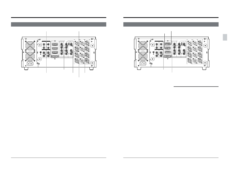
3-2 OUTPUT CONNECTIONS
[TIME CODE OUT]
[SERIAL V/A OUT]
[AUDIO OUT]
[AES/EBU OUT]
[COMPONENT OUT]
Set the component output level with menu switch No.
104
● All video parameter settings except SCH phase can
be adjusted. (See page 119.)
[AES/EBU OUT]
Install the optional SA-D95U digital interface board to
output signals from this connector.
[AUDIO MONITOR]
3 CONNECTIONS
[COMPONENT OUT]
[COMPOSITE OUT]
[SERIAL V/A OUT]
Install the optional SA-D95U digital interface board to
output signals from this connector.
● All video parameter settings except SCH phase can
be adjusted. (See page 119.)
[AUDIO OUT]
Set the audio output reference level with menu
switches No. 228 to 231
[TIME CODE OUT]
Select the time code output method during search
with menu switch No. 452
[AUDIO MONITOR]
Set the audio output reference level with menu
switches No. 232 and 233
[COMPOSITE OUT]
● On-screen data is output only to the [LINE 2 -
SUPER] connector.
● Select the main time code or sub time code to
output VITC with menu switch No. 451
● Video parameters can be adjusted. (See page 119.)
27
IN
CH1/2
CH1/2
CH3/4
CH3/4
OUT
IN
OUT
1
2
Y
Y
R-Y
B-Y
B-Y
R-Y
IN
OUT
OUT
OFF
ON
75
LINE1
LINE2
SUPER
RS-232C
COMPOSITE
LINE IN
REF
COMPONENT
COMPOSITE
REMOTE IN (9P)
REMOTE OUT (9P)
VIDEO CONTROL
CH1
CH2
CH3
CH4
CH2
CH3
CH4
CH1
IN
OUT
L
R
SERIAL V / A
SERIAL V / A
AES / EBU
AES / EBU
VIDEO
TIME CODE
AUDIO IN
AUDIO OUT
AUDIO MONITOR
3-3 CONTROL SYSTEM CONNECTIONS
3 CONNECTIONS
[REMOTE IN (9P)]
Connect an editing control for the RS-422 serial
interface.
Editing controller menu setting switches are available.
Menu switch No. 359
Menu switch No. 363
To control more than one VCR at the same time, set
menu switch No. 369
[RS-232C]
Connect to an RS-232C interface in a personal
computer or other control unit.
[REMOTE OUT (9P)]
Connect another VCR with an RS-422 interface. You
will be able to control the other VCR from this unit.
To control more than one VCR at the same time,
connect this connector to a [REMOTE IN] connector
of the subsequent VCR.
[VIDEO CONTROL]
Connect an optional TBC remote control to operate
the built-in TBC video controls. The RM-G22U
cannot be connected.
When adjusting with a video controller, press the
[VCON] button to select “Remote” and activate the
settings. (Refer to “EDITING SYSTEM PHASE
ADJUSTMENT” on page 117.)
Editing remote control connection
● Set the editing timing to -7 frames from the editing
remote control.
● The preroll time should be set to 5 seconds or
more.
● When using the RM-G820U or RM-G870U editing
remote controller, execute the editing controller's
learn function before operating. Otherwise, the
number of retries will be increased.
● When the RM-G820 remote controller is connected
to this unit, set the menu switch No. 317 < 9PIN
DEVICE ID > to “JVC D80”. The remote controller’s
edit timing is automatically set to -7 frames.
[REMOTE IN (9P)]
[RS-232C]
[REMOTE OUT (9P)]
[VIDEO CONTROL]