Intel WiFi Link 5100 User Manual
Page 19
Intel
®
5100 Memory Controller Hub Chipset for Communications, Embedded, and Storage Applications
July 2008
TDG
Order Number: 318676-003US
19
Intel
®
5100 MCH Chipset
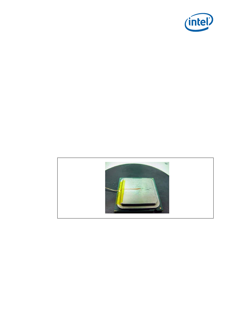
2. Place the thermocouple wire inside the groove letting the exposed wire and bead
extend about 3.2 mm (0.125") past the end of the groove. Secure it with Kapton
tape (
).
3. Lift the wire at the middle of groove with tweezers and bend the front of the wire to
place the thermocouple in the channel ensuring that the tip is in contact with the
end of the channel grooved in the IHS (
A and B).
4. Place the MCH under the microscope unit (similar to the one used in
) to
continue with the process. It is also recommended to use a fixture to help hold the
unit in place for the rest of the attach process.
5. Press the wire down about 6 mm (0.125") from the thermocouple bead using the
tweezers. Look in the microscope to perform this task. Place a piece of Kapton tape
to hold the wire inside the groove (
for detailed bead
placement.
6. Using the micromanipulator, place the needle near the end of groove on top of the
thermocouple. Using the X, Y, and Z axes on the arm, place the tip of the needle on
top of the thermocouple bead. Press down until the bead is seated at the end of the
groove on top of the step (see
and
).
7. Measure resistance from thermocouple end wires (hold both wires to a DMM probe)
to the IHS surface. This should be the same value as measured during the
thermocouple conditioning. See
, step
, and
.
8. Place a small amount of Locite* 498* Super Bonder* adhesive in the groove where
the bead is installed. Using a fine point device, spread the adhesive in the groove
around the needle, the thermocouple bead, and the thermocouple wires already
installed in the groove during step
Be careful not to move the thermocouple
bead during this step (
).
Figure 9.
Securing Thermocouple Wires with Kapton Tape Prior to Attach