Intel I815E User Manual
Page 24
INSTALLATIONS
20
I815E User’s Manual
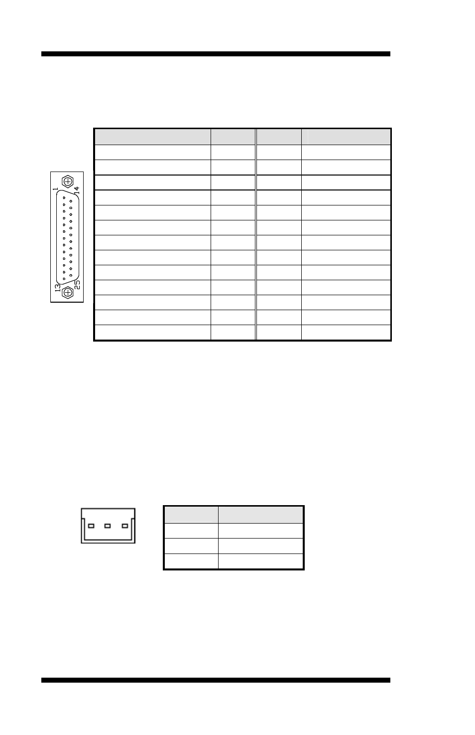
J10: Parallel Port Connector
J10 is a DB-25 external connector situated on top of the VGA and serial
ports. The following table describes the pin-out assignments of this
connector.
Signal Name
Pin #
Pin #
Signal Name
Line printer strobe
1
14
AutoFeed
PD0, parallel data 0
2
15
Error
PD1, parallel data 1
3
16
Initialize
PD2, parallel data 2
4
17
Select
PD3, parallel data 3
5
18
Ground
PD4, parallel data 4
6
19
Ground
PD5, parallel data 5
7
20
Ground
PD6, parallel data 6
8
21
Ground
PD7, parallel data 7
9
22
Ground
ACK, acknowledge
10
23
Ground
Busy
11
24
Ground
Paper empty
12
25
Ground
Select
13
N/A
N/A
J11: TV-Out Interface Connector
The J11 34-pin header is used to connect, through the use of a ribbon
cable, to the 34-pin header of an optional daughter card (IBD742)
containing the S-VHS and RCA connectors.
J13: Wake On LAN Connector
J13 is a 3-pin header for the Wake On LAN function on the board. The
following table shows the pin out assignments of this connector. Wake
On LAN will function properly only with an ATX power supply with
5VSB that has 200mA.
Pin #
Signal Name
1
+5VSB
2
Ground
1 2 3
3
-PME