I/o resources, Storage facility image 1, Storage facility image 2 – IBM DS8000 User Manual
Page 73: S-hmc, Cd/ dv d cd/ dv d
Chapter 3. Storage system LPARs (Logical partitions)
51
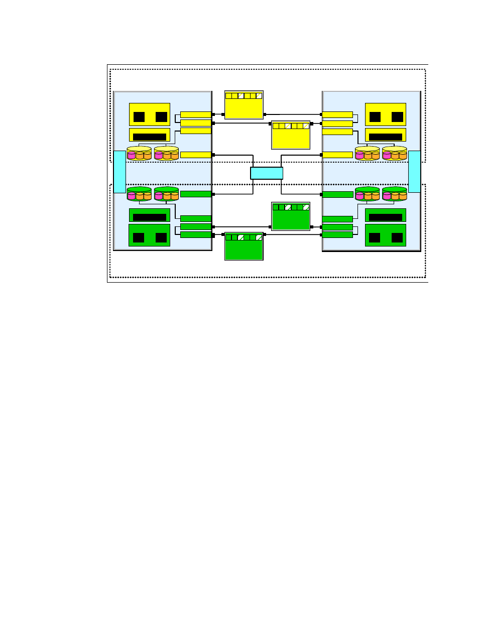
Figure 3-4 Storage facility image resource allocation in the processor complexes of the DS8300
I/O resources
For one storage facility image, the following hardware resources are required:
2 SCSI controllers with 2 disk drives each
2 Ethernet ports (to communicate with the S-HMC)
1 Thin Device Media Bay (for example, CD or DVD; can be shared between the LPARs)
Each storage facility image will have two physical disk drives in each processor complex.
Each disk drive will contain three logical volumes, the boot volume and two logical volumes
for the memory save dump function. These three logical volumes are then mirrored across the
two physical disk drives for each LPAR. In Figure 3-4, for example, the disks A/A' are mirrors.
For the DS8300 Model 9A2, there will be four drives total in one physical processor complex.
Processor and memory allocations
In the DS8300 Model 9A2 each processor complex has four processors and up to 128 GB
memory. Initially there is also a 50/50 split for processor and memory allocation.
Therefore, every LPAR has two processors and so every storage facility image has four
processors.
The memory limit depends on the total amount of available memory in the whole system.
Currently there are the following memory allocations per storage facility available:
32 GB (16 GB per processor complex, 16 GB per storage facility image)
64 GB (32 GB per processor complex, 32 GB per storage facility image)
128 GB (64 GB per processor complex, 64 GB per storage facility image)
256 GB (128 GB per processor complex, 128 GB per storage facility image)
Storage Facility Image 1
S-HMC
Processor complex 1
Processor complex 0
Processor complex 0
Processors
2 Processors
Memory
2 Processors
Memory
I/O drawer
0
HA
DA
HA
HA HA
DA
Processors
2 Processors
Memory
RIO-G interface
SCSI controller
Ethernet-Port
RIO-G interface
RIO-G interface
I/O drawer
1
HA
DA
HA
HA HA
DA
2 Processors
Memory
Ethernet-Port
RIO-G interface
Ethernet-Port
SCSI controller
RIO-G interface
RIO-G interface
Ethernet-Port
SCSI controller
RIO-G interface
RIO-G interface
Ethernet-Port
SCSI controller
RIO-G interface
RIO-G interface
RIO-G interface
SCSI controller
Ethernet-Port
RIO-G interface
RIO-G interface
I/O drawer
3
HA
DA
HA
HA HA
DA
I/O drawer
2
HA
DA
HA
HA HA
DA
CD/
DV
D
CD/
DV
D
Storage Facility Image 2
boot data data
boot data data
A
A'
boot data data
boot data data
B
B'
boot data data
boot data data
C
C'
boot data data
boot data data
D
D'