Hbdv7 series direct vent gas fireplace, Venting installation, Vertical through-the-roof installation – Monessen Hearth HBDV400N/PSC7 User Manual
Page 22
HBDV7 Series Direct Vent Gas Fireplace
54D8000
VeNtING INStAllAtIoN
•
7DVCS supports offsets. Figure 39. This application
will require that you first determine the roof pitch and
use the appropriate starter kit. (Refer to Venting Com-
ponents List)
•
The maximum angular variation allowed in the system
is 70°. Figure 36
•
For the minimum height of the vent above the highest
point of penetration through the roof refer to Page 23,
Figure 40.
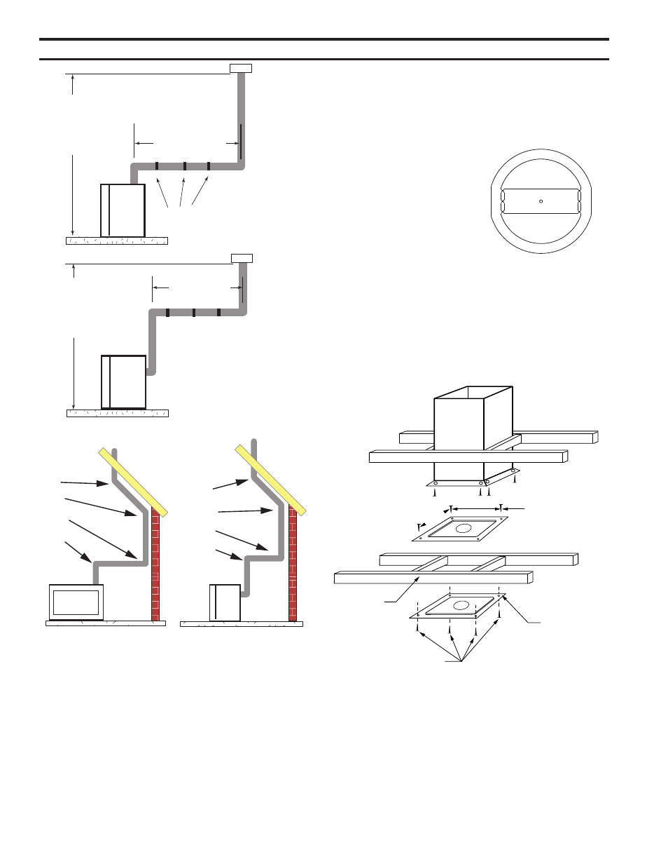
Support Straps
Every 3’ (914 mm)
Max.Height
40’ (1.. m)
Min. Height
8’ (.4 m)
Max. 10’ (3 m)
Max. 10’ (3 m)
Max.Height
40’ (1.. m)
Min. Height
8’ (.4 m)
FP1183a
Figure 35 -
Support Straps for
Horizontal Runs
1 + 2 + 3 + 4 = 270°
1
2
3
4
1
2
3
4
FP1179
max bends
FP1179
Figure 36 -
Maximum Elbow Usage
VeRtICAl tHRouGH-tHe-RooF
INStAllAtIoN
Note: For all top vent vertical through-the-roof instal-
lations, install the supplied cross-bar flue restrictor, part
#69D3006 onto the top edge of the firebox flue adapter.
Figure 37
1. Locate your fireplace.
. Plumb to center of the
(4”) flue collar from ceiling
above and mark position.
3. Cut opening equal to 9C\v” x
9C\v” (48 x 48 mm).
4. Proceed to plumb for addi-
tional openings through the
roof. In all cases, the open-
ing must provide a mini-
mum of 1 inch clearance to
the vent pipe, i.e., the hole
must be at least 9C\v” x 9C\v” (48 x 48 mm).
5. Place fireplace into position.
6. Place firestop(s) or Attic Insulation Shield into position
and secure. Figure 38
FP2304
CDV7 top restrictor
3/09
Figure 37 -
Vertical Through-the-Roof
Restrictor
FP304
FP1029
attic insulation shield
firestop spacers
1/28/00 djt
Attic Insulation
Shield
(7DV1AIS)
upper Floor
11”
(79 mm)
Ceiling Installation
Joist
Firestop
Spacer
Nails (4)
FP109
Figure 38 -
Place Firestop Spacer(s) and Secure
7. Install roof support (Figure 39) and roof flashing mak-
ing sure upper flange is below the shingles. Figure 41
8. Install appropriate pipe sections until the venting is
above the flashing. Figure 41
9. Install storm collar and seal around the pipe.