Hbdv7 series direct vent gas fireplace, Vent installation, Rear wall vent installations - flex vent pipe – Monessen Hearth HBDV400N/PSC7 User Manual
Page 17: Top vent sidewall application
HBDV7 Series Direct Vent Gas Fireplace
54D8000
17
VeNt INStAllAtIoN
FP2294
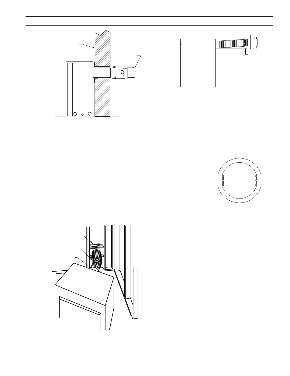
Side View Vent Termination
1/25/00 djt
Finish Wall
Vent
Termination
FP94
Figure 19 -
Side View of Final Unit Location
ReAR WAll VeNt INStAllAtIoNS -
Flex VeNt PIPe
Follow Steps 1 and on Page 16.
Step 3
Install the 4” (10 mm) flex vent pipe to the appliance col-
lars described in “General Information Assembling Vent
Pipes”, Page 13. If the installation requires a 45° angle,
grasp the vent pipe close to the appliance collar and bend
to 45°. DO NOT exceed 45°. Figure 20
Install the 7” vent pipe in the same manner as Step .
Note: There must be a 1/” (13 mm) rise in a 1” (305
mm) length of flex vent.
Step 4
Assemble the flex vent to the collars on the termination as
you did on the appliance.
FP1473
corner flex install
4/04 djt
Termination
Flex Section
Appliance Collars
FP1473
Figure 20 -
Grasp the vent pipe close to the collar and
bend to 45° angle. do not exceed 45°.
FP1472
rise in length
4/04 djt
Rise
FP147
Figure 21 -
There must be a 1/2" rise per foot length
toP VeNt SIDeWAll APPlICAtIoN
Note: For all top vent installations where a 90° elbow is
the first pipe piece towards a sidewall termination (up and
out), an open-center ringed flue restrictor, part #69D3006
must be installed onto the top edge of the firebox flue
adapter. To create this open-center restrictor, twist and
break off the center rib of the supplied flue restrictor. The
installed part should appear similar to that show n in Fig-
ure 22.
Since it is very important
that the venting system
maintain its balance be-
tween the combustion air
intake and the flue gas
exhaust,
certain
limitations as to
vent configurations
apply and must be
strictly adhered to.
The Vent Graph, showing the relationship between verti-
cal and horizontal side wall venting, will help to determine
the various dimensions allowable.
Minimum clearance between vent pipes and combus-
tible materials is 3" (76 mm) on top, and 1" (25 mm) on
the bottom and sides unless otherwise noted.
When vent termination exits through foundations less
than 0” (508 mm) below siding outcrop, the vent pipe
must flush up with the siding.
It is best to locate the fireplace in such a way that mini-
mizes the number of offsets and horizontal vent length.
The horizontal vent run refers to the total length of vent
pipe from the flue collar of the fireplace (or the top of the
Transition Elbow) to the face of the outer wall.
Horizontal plane means no vertical rise exists on this por-
tion of the vent assembly.
FP2303
CDV7 rear restrictor
3/09
Figure 22 -
Top Vent Vertical Sidewall
Restrictor
FP303