Middleby Cooking Systems Group PS360/PS360WB User Manual
Page 37
2-23
SECTION 2
INSTALLATION
VI. ELECTRICAL CONNECTION
Check the oven data plate before making any electric supply
connections. Electric supply connections must agree with data
on the oven data plate. A typical oven data plate is shown in
Figure 2-34 (on Page 2-24).
NOTE: When the oven is installed, it must be electrically
grounded in accordance with current IEC/CEE requirements
and also with local codes.
The electrical installation, including the service connection,
must comply with current IEC/CEE requirements and to local
codes. The installation must undergo a complete electrical
check before operating the oven.
Special attention must be given to the polarity of the supply
when connecting to oven input terminals.
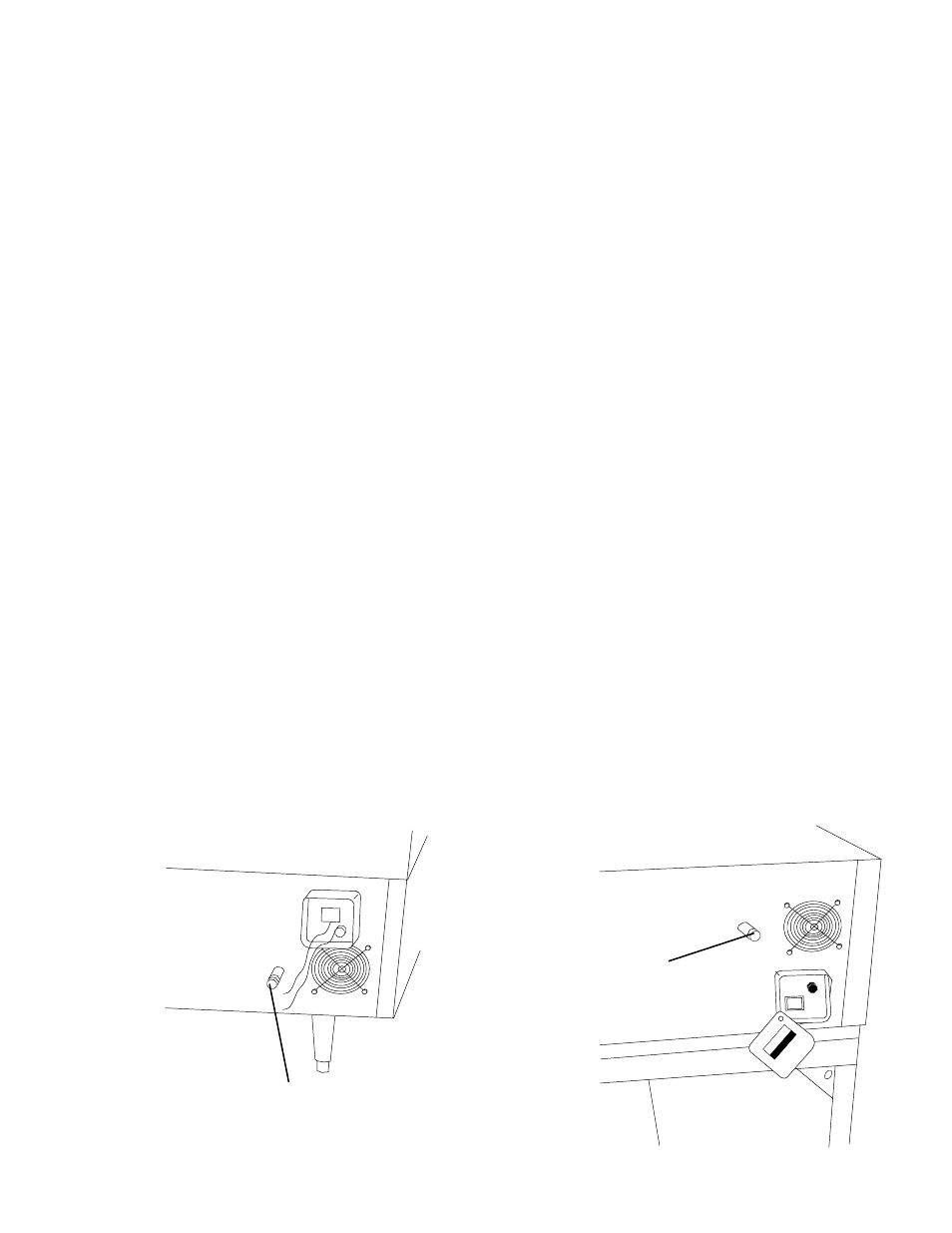
All connections are made at one common connection at the
back of each oven. Refer to Figures 2-32 and 2-33.
NOTE: At the installation location, it is required that the
electrical supply for each oven incorporates a main circuit
breaker (not furnished). The circuit breaker must have 3mm
contact gaps breaking all poles of the supply.
WARNING: If your electrical supply has fast-acting circuit
breakers, then the initial starting current of the blower motors
in Model PS360WB-U and PS360WB-L may trip the breakers.
It is suggested to use slow-acting circuit breakers with these
models.
For further electrical information, refer to the wiring diagram.
WARNING: The connections to the exhaust system, electrical
supply, and gas supply must follow the installation instructions.
Initial start-up of the oven can be performed only by an
authorized agent.
Figure 2-32
Junction Connection Box (Lower Oven)
Figure 2-33
Junction Connection Box (Upper Oven)
3/4 (19mm) pipe for gas oven connection
3/4 (19mm) pipe for gas
oven connection