Front panel connectors: jfp1 & jfp2, Front panel i/o connectivity design guide, Hardware setup 2-17 – MSI G52-MA00628 User Manual
Page 32: Jfp1 (intel spec), Jfp2
Hardware Setup
2-17
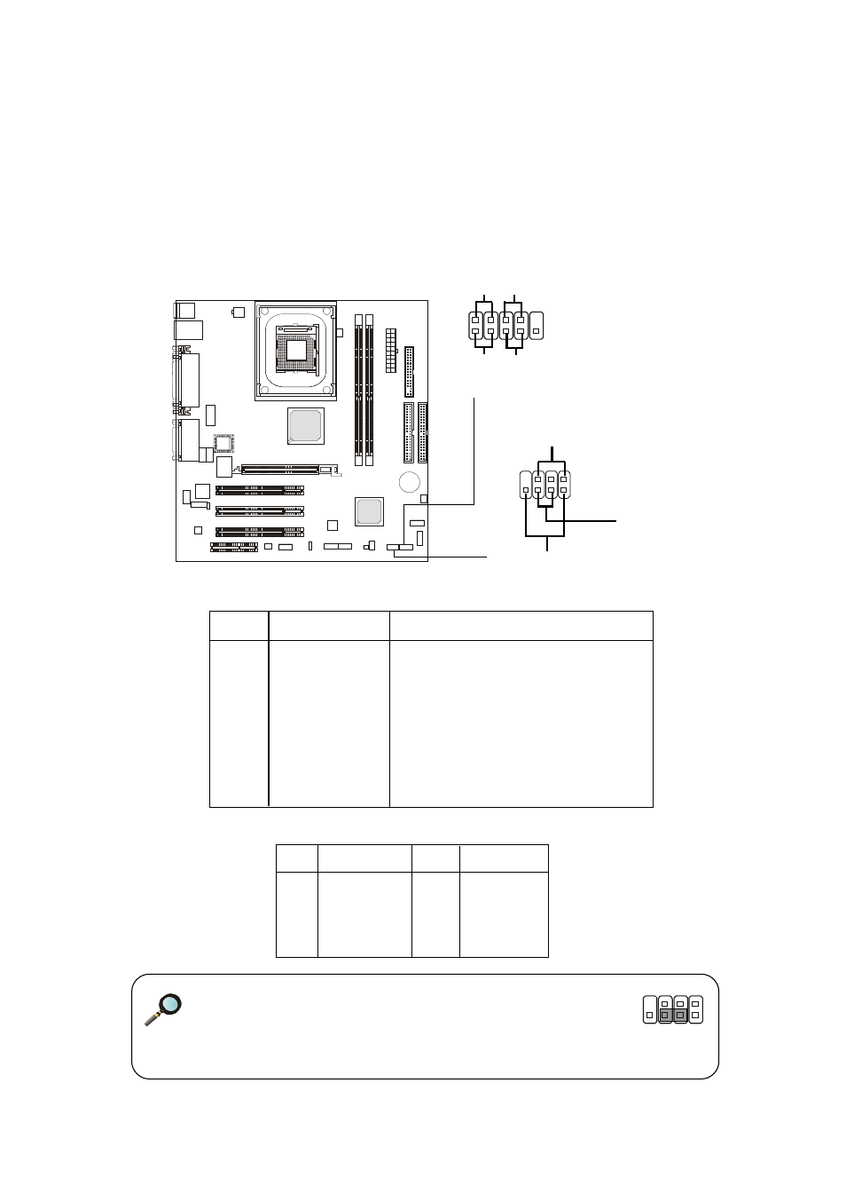
Front Panel Connectors: JFP1 & JFP2
The mainboard provides front panel connectors for electrical connection
to the front panel switches and LEDs. Users can choose either the JFP1 or the
JFP2 depending on their needs. JFP1 is compliant with Intel
®
Front Panel I/O
Connectivity Design Guide.
PIN
SIGNAL
DESCRIPTION
1
HD_LED_P
Hard disk LED pull-up
2
FP PWR/SLP
MSG LED pull-up
3
HD_LED_N
Hard disk active LED
4
FP PWR/SLP
MSG LED pull-up
5
RST_SW_N
Reset Switch low reference pull-down to GND
6
PWR_SW_P
Power Switch high reference pull-up
7
RST_SW_P
Reset Switch high reference pull-up
8
PWR_SW_N
Power Switch low reference pull-down to GND
9
RSVD_DNU
Reserved. Do not use.
JFP1 Pin Definition
Note for JFP2:
If onboard buzzer is available, you can short pins 4 & 6 to
have the buzzer enabled or open pins 4 & 6 to have the
buzzer disabled.
JFP1
(Intel spec)
1 9
2 10
HDD
LED
Reset
Switch
Power
LED
Power
Switch
JFP2
6 4
PIN
SIGNAL
PIN
SIGNAL
1
GND
2
SPK-
3
SLED
4
BUZ+
5
PLED
6
BUZ-
7
NC
8
SPK+
JFP2 Pin Definition
JFP2
Speaker
8 2
7 1
Power LED
Buzzer
(short pin)