Chapter 2 2-10, Pin male din connectors, Jcom3 – MSI G52-MA00628 User Manual
Page 25
Chapter 2
2-10
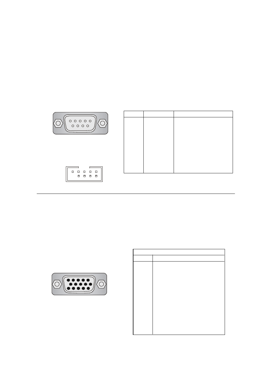
9-Pin Male DIN Connectors
PIN
SIGNAL
DESCRIPTION
1
DCD
Data Carry Detect
2
SIN
Serial In or Receive Data
3
SOUT
Serial Out or Transmit Data
4
DTR
Data Terminal Ready
5
GND
Ground
6
DSR
Data Set Ready
7
RTS
Request To Send
8
CTS
Clear To Send
9
RI
Ring Indicate
Pin Definition
Serial Port Connectors: COMA & COMB (for SiS645DX) /
JCOM3 (for SiS650GX/651)
The mainboard offers two 9-pin connectors as serial port COMA & COMB
/ JCOM3. The ports are 16550A high speed communication ports that send/
receive 16 bytes FIFOs. You can attach a serial mouse or other serial devices
directly to the connectors.
JCOM3
9 8 7 6
5 4 3 2 1
VGA DB 15 Pin Connector (for SiS650GX/651 only)
One optional DB 15-pin VGA connector is provided for connection to a
VGA monitor.
DB 15-Pin Female Connector
5 1
15 11
Analog Video Display Connector (DB-15S)
PIN
SIGNAL DESCRIPTION
1
Red
2
Green
3
Blue
4
Not used
5
Ground
6
Ground
7
Ground
8
Ground
9
Power
10
Ground
11
Not used
12
SDA
13
Horizontal Sync
14
Vertical Sync
15
SCL
Pin Definition
1 2 3 4 5
6 7 8 9