Electrical wiring (milli-volt), Connecting remote receiver, Installing t-stat sensor (option sold separately) – Monessen Hearth HVFL18 User Manual
Page 23
59D1015
23
HIG
H
LOW
26D
3317
THE
RM
OST
AT
SET
TING
HIG
H
LOW
26D
3317
THE
RM
OST
AT
SET
TING
ELECTRICAL WIRING (MILLI-VOLT)
CONNECTING REMOTE RECEIVER
THESE INSTRUCTIONS SUPERCEDE THE SECTION
ENTITLED “HEARTH MOUNT” IN THE MILLI-VOLT
HAND-HELD REMOTE INSTRUCTIONS SUPPLIED
WITH THE REMOTE.
1. Cut cable to length (approximately 12") for placement
in the fireplace.
2. Strip back
1
/
4
" of the insulation from both ends of
each wire.
3. Connect two .25 female connectors to the wires at one
end of the cable.
4. Insert the opposite end into receiver (special fitting on
Ambient remotes).
5. Connect the connectors to the two .25" male connectors
located on the right side when facing the unit (Figure 19).
Do not let the wire touch the grate or burners.
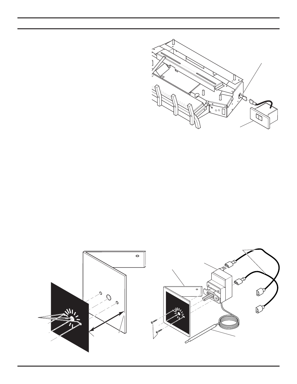
Figure 19 - Installing Remote Receiver
Remote
Receiver
6. Stick velcro pads with self-adhesive backing to side of remote receiver and to the right side of the unit. See
Figure 19.
7. Attach remote receiver with velcro pads. Control switch must face forward.
NOTE: Heat reduces battery life. You can protect the receiver and extend battery life by mounting the
receiver in a wall or other location outside the fireplace.
Remote
Wire
Connectors
Figure 20 - Applying Label to Bracket
Flush edge of label to
right side of bracket
Line Up
Holes
INSTALLING T-STAT SENSOR (OPTION SOLD SEPARATELY)
1. Remove metal bracket and label from box.
2. Peel away the paper backing on the label. Line up holes in label with holes on the bracket. Right side of label should
flush with right side of bracket. See Figure 20. Press label firmly and smoothly to bracket.
3. Using Phillips screwdriver, install t-stat sensor to bracket with two screws provided. See Figure 21. Make sure the
thermo bulb wire is at the bottom of t-stat sensor.
4. Plug in wiring harnesses to back of t-stat sensor. See Figure 21.
Figure 21 - Installing T-Stat Sensors
and Wiring Harnesses
Wiring
Harnesses
T-Stat
Sensor
Bracket
Screws
Thermo Bulb