Connection with rs-232c equipment – MITSUBISHI ELECTRIC CP900E User Manual
Page 15
15
CONNECTIONS
PRINTING
ADJUSTMENTS
PRECAUTIONS
FEA
TURES
PREP
ARA
TION
OTHERS
TROUBLE-
SHOOTING
RS-232 Connection Cable
Computer (DB9)
Printer (DB25)
Signal
Pin No.
Pin No.
Signal
RXD
2
2
TXD
TXD
3
3
RXD
DR
4
6
DSR
SG
5
7
GND
DR
6
20
DTR
RS
7
5
CTS
CS
8
4
RTS
FG
9
1
FG
•
#9 on the 9 Pin end of the cable is typically tied to the Shield.
•
This is just an example. Make sure to check the connection type
for the using equipment.
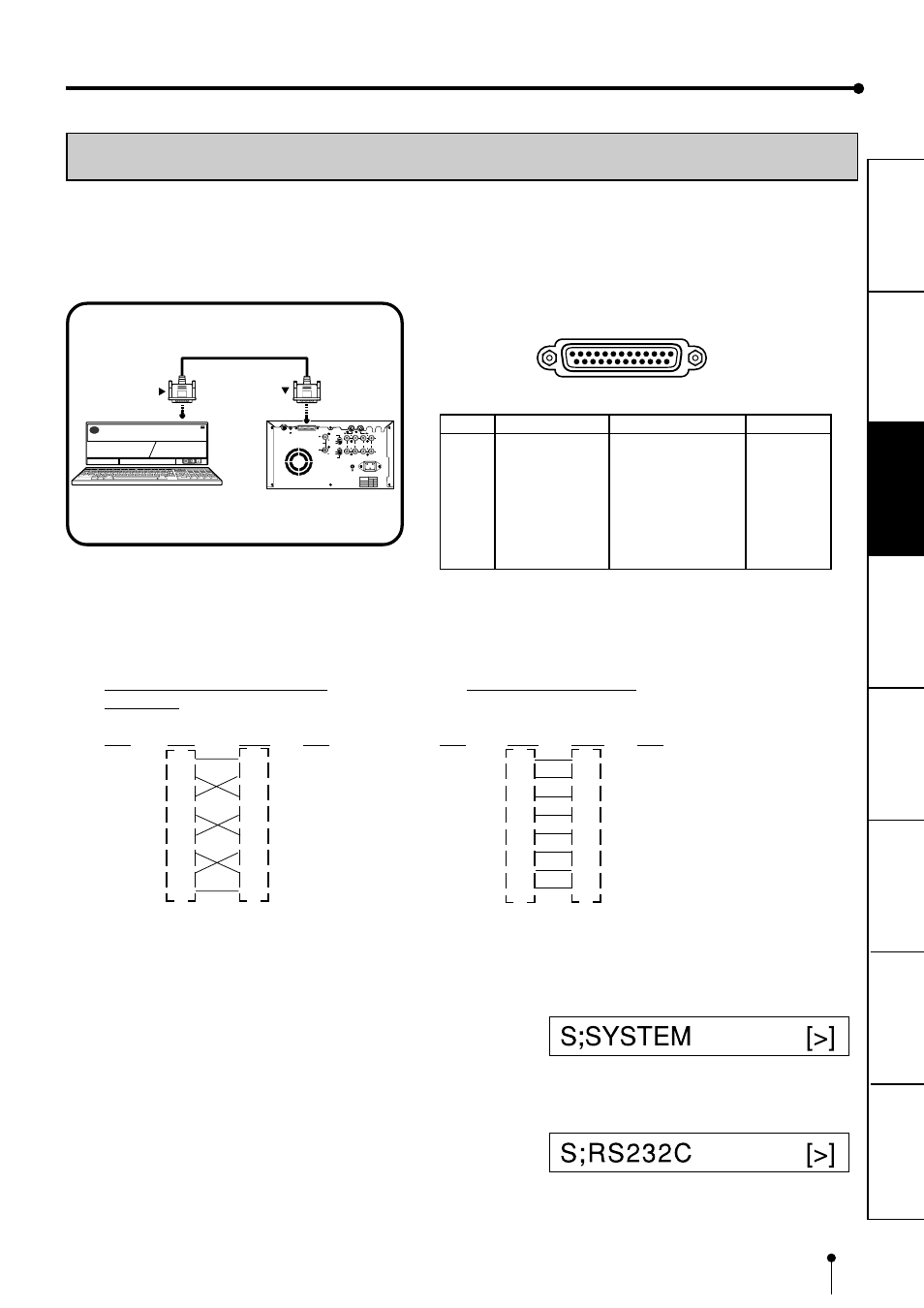
CONNECTION WITH RS-232C EQUIPMENT
This unit can controlled through a RS-232C port with custom software. (Image data can not be input.)
For the protocol, consult your dealer.
Make sure to turn off the power before setting.
2
2
2
2
2
RS-232C TERMINAL SIGNAL
REMOTE
RS-232C
S-VIDEO IN
S-VIDEO OUT
R
G/G+SYNC
B
Y/SYNC
IN
VIDEO
75
Ω
75
Ω
/HIGH
AC LINE
OUT
75
Ω
/HIGH
75
Ω
75
Ω
75
Ω
75
Ω
HIGH
HIGH
HIGH HIGH
ON
OFF
POWER
HIGH
IMPEDANCE
RGB
75
Ω
75
Ω
/HIGH
HIGH
SYNC
To RS-232C terminal
(RS-232C)
To RS-232C treminal
VCP
Equipment with RS-232C
25
14
13
Pin number
1
Pin No. Signal line name
Description
Directions
1
FG
Protective
---
2
TXD
Transmitted data
Output
3
RXD
Received data
Input
4
RTS
Request to send
Output
5
CTS
Clear to send
Input
6
DSR
Data set ready
Input
7
GND
Signal ground
---
20
DTR
Data terminal ready
Output
RS-232 Connection Cable (Cross-
over cable)
(DB25)
(DB25)
Signal Pin No.
Pin No.
Signal
FG
1
1
FG
TXD
2
2
TXD
RXD
3
3
RXD
RTS
4
4
RTS
CTS
5
5
CTS
DSR
6
6
DSR
DTR
20
20
DTR
GND
7
7
GND
1
1
1
1
1
Connect this unit and RS-232C equipment
with a crossover cable.
2
2
2
2
2
Set the baud rate according to the equipment
to be connected.
Press MENU button, then press STOP button
on remote control unit.
SERVICE MENU is displayed.
3
3
3
3
3
Press
}
}
}
}
}
button to select “RS232C.”