4) ignition system checks – Gas-Fired Products PTS Series 100 User Manual
Page 49
Form
#43343530
–48–
JJuly 08
3. Connect plastic tubing of a digital or inclined water manometer with a 0-2” scale onto the connector tees.
4. Turn heater on and wait until blower motor is activated.
5. Observe air pressure from manometer. This should be higher than the set point indicated below for correct
operation.
Model
Operating Pressure
Model
Operating Pressure
PTS/U 40/25
0.98” W.C. Hot
PTS/U 125/80
0.39” W.C. Hot
PTS/U 50/30
0.98” W.C. Hot
PTS/U 150/100
0.39” W.C. Hot
PTS/U 75/50
0.70” W.C. Hot
PTS/U 175/110
0.39” W.C. Hot
PTS/U 100/65
0.70” W.C. Hot
PTS/U 200/125
0.39” W.C. Hot
All pressures are with the heater in operation for at least 15 minutes.
23.4)
IGNITION SYSTEM CHECKS
TO CHECK FLAME SENSOR CIRCUIT.
Flame current is the current which passes through the flame from the sensor to ground. The minimum flame
current necessary to keep the system from lockout is 0.7 microamps.
a) Turn off heater at thermostat.
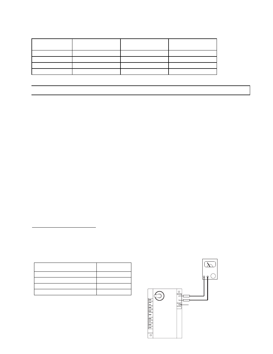
b) Connect a meter (dc microammeter scale) in series with the ground lead as shown in the diagram. Connect the
meter as follows:
Connect the black (negative) meter lead to the electronic control FC- terminal.
Connect the red (positive) meter lead to the electronic control FC+ terminal.
c) Restart the system and read the meter. The flame sensor current must be steady and measure at least 0.7
microamps.
d) If the meter reads less than the minimum or if reading is unsteady:
Make sure burner flame is capable of providing a good rectification signal.
Make sure fasteners securing igniter/sensor are tightened to assure correct positions. DO NOT relocate
igniter/sensor.
Check for excessive (over 1000ºF) temperature at ceramic insulator on flame sensor. Excessive temperature
can cause short to ground. DO NOT relocate igniter/sensor.
Check for cracked ceramic insulator, which can cause short to ground, and replace sensor if necessary.
Make sure that electrical connections are clean and tight. Replace damaged wire.
e) If the meter reads below “0” on the scale, meter leads are reversed. Disconnect power and reconnect meter
leads for proper polarity.
f) Remove microammeter. Return system to normal operation.
IGNITION MODULE DIAGNOSTICS
Flame Fault
If at any time the main valve fails to close completely and maintains a flame, the full time flame sense circuit will
detect it and energize the combustion blower. Should the main valve later close completely removing the flame
signal, the combustion blower will power off following the post purge period.
Fault Conditions
The LED located on the ignition module will flash ON
for ¼ second, then OFF for ¼ second during a fault
condition. The pause between fault codes is 3
seconds.
Error Mode
LED Indication
Internal Control Failure
Steady On
Air Flow Fault
1 Flash
Gas valve failure (stuck open) 2 Flashes
Ignition Lockout
3 Flashes
MULTIPURPOSE METER
USE
MICROAMP
SCALE
BLACK (-)
RED (+)
LED Display
GND
V2
FC-
FC+
V1
(W)TH
Ignition Module (Fenwal)
Flame Sensor Current Check
(R) 24VAC
L1
IND
NC
P.SW
S1