Gas-Fired Products PTS Series 100 User Manual
Page 45
Form
#43343530
–44–
JJuly 08
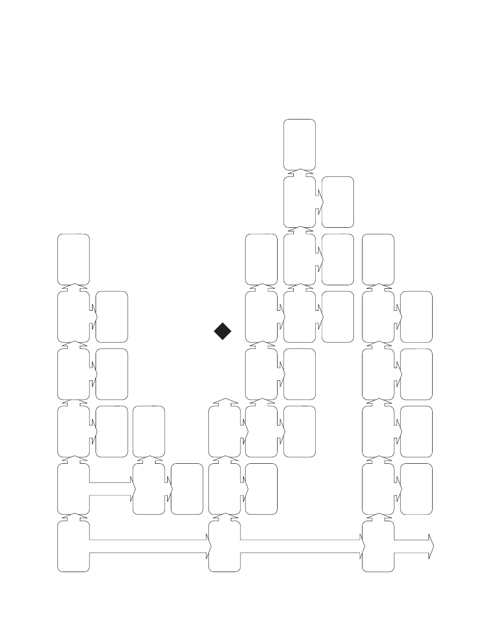
Check external thermost
at
w
iring
and
thermost
at set point.
No
Ye
s
Remove red wire from the Low fire terminal,
is
there
24V
at the center C terminal?
No
Ye
s
Is
there
24V
at
the
HI
terminal on the gas valve?
No
Ye
s
With the thermost
at
set to low fire only does the low fire amber light come on af
ter 15 seconds?
No
Ye
s
Is
there
24V
between
the thermost
at
terminal
block
low
fire
cont
act and ground?
No
Ye
s
Check terminal connections, is the yellow wire connected
to
the
high
fire terminal?
Check external thermost
at
w
iring
and
thermost
at set point.
Switch terminal connections.
Red
wire
LO should be connected to ignition module W (TH) terminal.
Rep
air terminal
connections. Rest
art
troubleshooting.
No
Ye
s
Are the black wires to the amber light securely on the gas valve terminals?
Rep
air connection.
Rest
art
troubleshooting.
Replace amber light. Rest
art
troubleshooting.
No
Ye
s
Does the low fire amber light st
ay on
past 10 seconds?
No
Ye
s
Check the micro Amp
s at the FC-FC+
terminals of the module is it greater than
0.7µA
with
flame.
Turn on the gas valve?
Does LED on the ignition module flash three times?
Replace ignition module.
Check flame sense wire does it have continuity?
Cont
act factory for
assist
ance.
Replace flame sense wire.
Adjust terminal connection. Rest
art
troubleshooting.
No
Ye
s
Is
the
knob
on
the
gas
valve turned to the ON position?
No
Ye
s
Through the inspection window is there a flame visible during st
art up?
No
Ye
s
Is
the
heater
properly
grounded?
Correct grounding problem.
No
Ye
s
Check
the
terminal
on
the flame sense electrode, is it tight?
No
Ye
s
Remove and inspect flame sense electrode. Is it clean and the ceramic int
act?
Rep
air or replace
flame sense electrode.
See next p
age for
troubleshooting sequence.
No
Ye
s
Replace ignition module.
No
Ye
s
No
Ye
s
Is
there
24V
at
the
HI
terminal on the gas valve?
No
Ye
s
Does the high fire amber
light
come
on?
No
Ye
s
Is the there 24V between the thermost
at terminal
block
high
fire
cont
act
and ground (yellow wire)?
No
Ye
s
Check terminal connections to the gas valve, are they tight?
Check the red wires C should be connected
to
the
TISS
and LO connected to W (TH) module terminal.
Rep
air terminal
connections.
Rep
air terminal
connections. Rest
art
troubleshooting.
No
Ye
s
Are the black wires to the amber light securely on the gas valve terminals?
Rep
air connection.
Rest
art
troubleshooting.
Replace amber light. Rest
art
troubleshooting.
Troubleshooting continued
on
the
next
page.