0) sequence of operation – Gas-Fired Products PTS Series 100 User Manual
Page 41
Form
#43343530
–40–
JJuly 08
19.0)
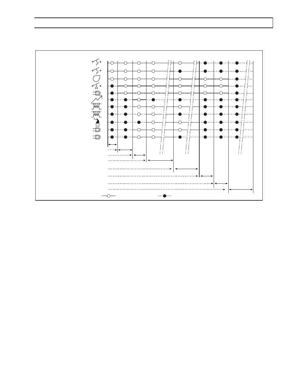
SEQUENCE OF OPERATION
The chart below shows the sequence of operation for the normal operating cycle of the PTS/PTU when connected
to a permanent 120V power supply and the heater is turned on and off by a remote 24V thermostat. (Electrical
connection diagram B).
T0 T1
T2
T3
T4
T5
T8
Call for heat, Thermostat on
15 secs pre-purge
15 secs trial for ignition
Normal high fire operation
flame sensing
Heater OFF
Thermostat (turn off)
30 secs post-purge
T7
Thermostat low fire
Blower
Red power light
Ignition
Air switch
Gas valve low fire
Flame sensing
Amber valve light - low fire
Function ON
Function OFF
Thermostat high fire
Gas valve low fire
Gas valve high fire
Amber valve light - high fire
Thermostat - high fire off
T6
If the flame is not sensed during sequence T3 then the burner will automatically begin re-ignition sequence T2. The
ignition sequence will be repeated three times with a 60 second inter-purge. If the flame is not re-established the
heater will go to lockout.