Gas-Fired Products PTS Series 100 User Manual
Page 20
Form #43343530
July 08
–19–
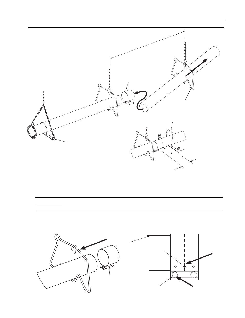
10.1
ASSEMBLY OF EXTENSION SECTION
See typical assembly overview (Section 8.0) for typical complete assembly. Assemble additional extension
sections as required for all systems. (See Sections 7.0, and 8.0 for typical layout details.)
Join the tube sections together and secure with tube couplings as described below:
WARNING: THE FOLLOWING COUPLING TIGHTENING INSTRUCTIONS MUST
BE FOLLOWED PROPERLY TO AVOID FUTURE PROBLEMS.
1. Place the compression coupling over the end of the tube.
2. Use the small hole at the centerline of the coupling to check that the coupling is inserted correctly.
3. Partially tighten the bolt nearest the end of the tube (approximately half closed).
MIN 8 MAX 10 BETWEEN HANGERS
1
2
Tube Support/
Hanger Bracket
Wire Hanger
Coupling
U-Bolt Clamp
& 5/16 Hex Nuts
Tube Support/
Hanger Bracket
3
6 approx.
Tube
Coupling
1
Center end of
Tube with hole
Partially tighten this bolt
Tube
2
3