Site considerations, Mounting to shop floor notice, Floor load – Grizzly Extren Series Jointer g9860 User Manual
Page 17: Placement location, Bolting to concrete floors
Extreme series Jointer (Mfg. since 9/11)
-15-
Floor Load
refer to the
Model Specification comparison
chart on
page 5 for the weight and footprint speci-
fications of your machine. some residential floors
may require additional reinforcement to support
both the machine and operator.
placement Location
Consider existing and anticipated needs, size of
material to be processed through each machine,
and space for auxiliary stands, work tables or
other machinery when establishing a location for
your new machine. see
Figures 11–12 for the
minimum working clearances.
children and visitors may be
seriously injured if unsuper-
vised around this machine.
Lock entrances to the shop
or disable start switch or
power connection to prevent
unsupervised use.
Site considerations
Figure 11. Minimum working clearances.
A
B
although not required, we recommend that you
mount your new machine to the floor. Because
this is an optional step and floor materials may
vary, floor mounting hardware is not included.
generally, you can either bolt your machine to
the floor or mount it on machine mounts. Both
options are described below. Whichever option
you choose, it is necessary to level your machine
with a precision level.
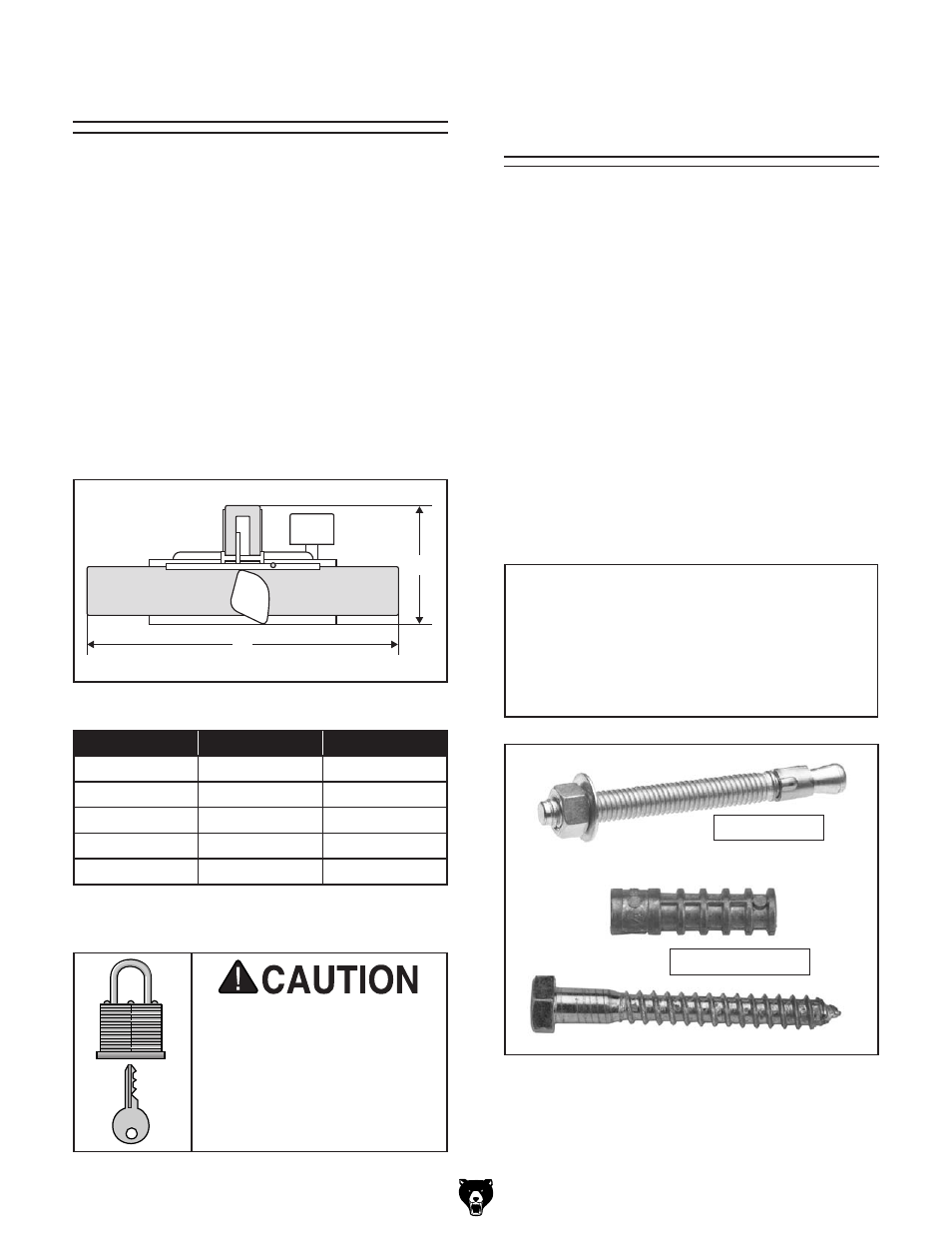
bolting to concrete Floors
anchor studs and lag shield anchors with lag bolts
(
Figure 13) are two popular methods for anchor-
ing an object to a concrete floor. We suggest
you research the many options and methods for
mounting your machine and choose the best that
fits your specific application.
Mounting to Shop
Floor
NOTICE
anchor studs are stronger and more per-
manent alternatives to lag shield anchors;
however, they will stick out of the floor,
which may cause a tripping hazard if you
decide to move your machine.
Figure 13. typical fasteners for mounting to
concrete floors.
anchor studs
lag shield & Bolt
Model
a
b
g9860
80"
35"
g9860zX
80"
35"
g9953
99
1
⁄
2
"
45
1
⁄
2
"
g9953zX
99
1
⁄
2
"
45
1
⁄
2
"
g9953zXF
99
1
⁄
2
"
45
1
⁄
2
"
Figure 12. Minimum working clearances by
model.