Notice, Stand beginning assembly – Grizzly G0444 User Manual
Page 20
-18-
G0444/G0444Z 10" Table Saw
Loose hair and clothing
could get caught in
machinery and cause
serious personal injury.
Keep loose clothing
rolled up and long hair
tied up and away from
machinery.
Sharp edges on metal
parts may cause person-
al injury. Examine the
edges of all metal parts
before handling.
This section will cover the basic assembly and
adjustment instructions needed to begin opera-
tion. Complete the assembly in the order provid-
ed in this manual and then read the remaining
portion of the manual before attempting any type
of operation.
Your safety is important! Please follow the
warnings below during this entire section:
!
Disconnect power to
the machine during the
entire assembly
process. Failure to do
this may result in seri-
ous personal injury.
Components and Hardware Needed:
Qty
Saw ....................................................................1
Stand Legs ........................................................4
Side Supports
• Long Flat ......................................................2
• Long Short ....................................................2
• Long “L” ........................................................2
• Short “L”........................................................2
Carriage Bolts
5
⁄
16
"-18 x
5
⁄
8
" ..............................40
Hex Bolts
5
⁄
16
"-18 x 1 ........................................4
Hex Nuts
5
⁄
16
"-18 ..............................................44
Flat Washers
5
⁄
16
" ..............................................48
Lock Washers
5
⁄
16
" ............................................44
Tools Needed:
12mm Wrench or Socket ....................................1
To assemble the stand:
1.
With the help of an assistant, place the saw
face-down on the floor. Note—
Lay clean and
staple-free cardboard down to protect the
table surface.
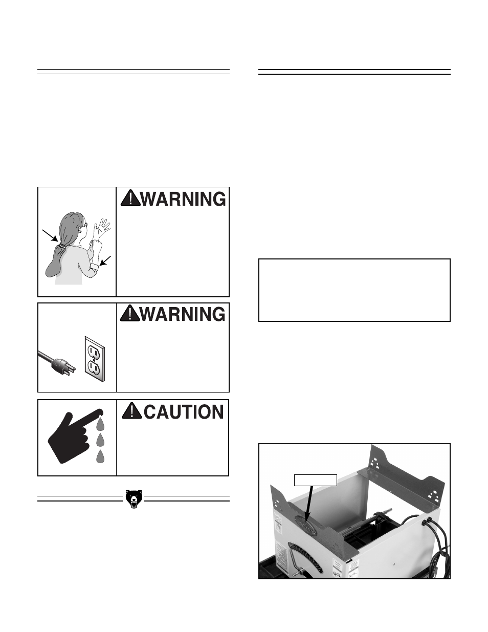
2.
Place the short “L” side supports on the bot-
tom of the saw body (
Figure 12
). Note—
Make sure the cast logo is facing the front of
the machine.
NOTICE
Do not final tighten the stand bolts until all
the stand components have been
assembled and the saw is rightside-up.
Figure 12.
L side support installation.
Stand
Beginning Assembly
Cast Logo