Sprayer parts list – Graco Inc. 231-353 User Manual
Page 35
308-548
35
Sprayer Parts List
Model 231–353, Series A
Includes items 3 to 89 as listed below
Ref.
No. Part No.
Description
Qty.
Ref.
No. Part No.
Description
Qty.
4{
236–965 MOTOR KIT
Includes items 4a to 4g
1
4a.
100–069 .BALL, sst,
1/4” dia.
1
4b.
111–616 .TERMINAL,
flat, 1/4” (f), 18 awg
2
4c.
107–503 .TERMINAL,
3/16” (m), 16 awg
1
4d.
107–267 .TERMINAL,
3/16” (f)
1
4e.Y 187–784 .LABEL, DANGER,
French
1
4f.Y 187–791 .LABEL, DANGER,
English
1
4g.Y 187–975 .LABEL, WARNING,
electric shock
1
6
105–510 LOCKWASHER,
1/4”
3
11
224–965 DRIVE HOUSING KIT
1
Includes item 11a, 11b
11a
100–069 .BALL,
stainless steel, 1/4” dia.
1
11b
111–726 .PLUG
1
12
224–803 CRANKSHAFT
1
Includes items 12a, 12b
12a
180–131 .BEARING,
thrust
1
12b
107–434 .BEARING
1
13
188–366 COVER,
front
1
14Y 177–762 LABEL, WARNING
1
15
218–359 CONNECTING ROD
1
16
218–364 GEAR REDUCER
1
17
176–818 PIN,
headless, 3/8” dia. x 1”
1
18
176–817 SPRING,
retaining
1
19
103–345 SCREW,
socket head,
5
1/4–20 x 1–1/4”
20
236–787 PUMP KIT
1
see parts on page 29
21
111–706 CAPSCREW,
7/16–14 x 1–3/4”
2
23
111–715 SCREW,
5/16–18 x 1–1/4”
4
24
190–337 HANDLE,
sprayer
1
25
112–759 CAP,
tubing
4
28
162–453 NIPPLE,
hex, 1/4 npsm x
2
1/4 npt, 1–3/16”
29
235–009 PRESSURE TRANSDUCER
1
30
190–464 CLIP,
5/8”
1
31
108–850 SCREW,
filh, 8–32 x 1–1/4”
1
32
237–684 SUCTION HOSE & TUBE
1
33
190–336 DRAIN TUBE
1
34
111–705 SCREW,
filh, 8–32 x 2–1/2”
3
35
290–072 LABEL
, identification
1
36
237–696 ELBOW, drain
1
37
190–334 LEG,
sprayer
2
38
190–451 ADAPTER, union
1
39
237–820 STRAINER
1
42
235–014 DRAIN VALVE KIT
1
Includes items 42a to 42e
42a
111–699 .GASKET,
valve seat
1
42b
187–615 .SEAT,
drain valve
1
42c
224–968 .STEM,
drain valve
1
42d
168–110 .O–RING,
stem
1
42e
110–110 .SEALANT,
pipe (not shown)
1
43
224–807 BASE,
valve
1
44
111–600 PIN,
grooved, 3/32 x 1”
1
45
187–625 HANDLE,
drain valve
1
46
110–997 SCREW,
washer/hex hd, 5/16”
2
47
235–008 MOTOR START BOARD
1
48Y 186–620 LABEL,
ground terminal
1
49
110–037 SCREW,
mach, pnhd, 10–24 x 5/8”
1
50
235–010 POWER CORD SET
1
51
111–617 STRAIN RELIEF BUSHING,
1
3/8–18 npt
52
105–679 SWITCH, ON/OFF
1
53
235–035 GROUND HARNESS
1
54
105–658 LOCKING RING
1
55
105–659 BOOT
, switch
1
56
111–703 SCREW,
filh, 10–24 x 3”
4
58
100–035 SCREW,
pan hd, 8–32 x 5/16”
2
59
187–795 JUNCTION BOX
1
63
111–704 SCREW
, filh, 10–24 x 1–5/8”
2
64
224–828 PRESSURE CONTROL KIT
1
66
189–932 BASE,
motor
1
67
238–350 FTx GUN
1
See manual 308–645 for parts
68
206–994 TSL,
8 oz. (not shown
)
1
74
238–361 HOSE,
grounded, nylon; 1/4” ID;
1
cpld 1/4 npsm(f); 50 ft (15 m);’
spring guards both ends
79
103–473 STRAP, tie
2
89
187–963 GASKET
1
Y Extra warning labels available free of charge.
{
Motor Brush and Spring Replacement Kit,
P.N.236–967 is available. Purchase separately.
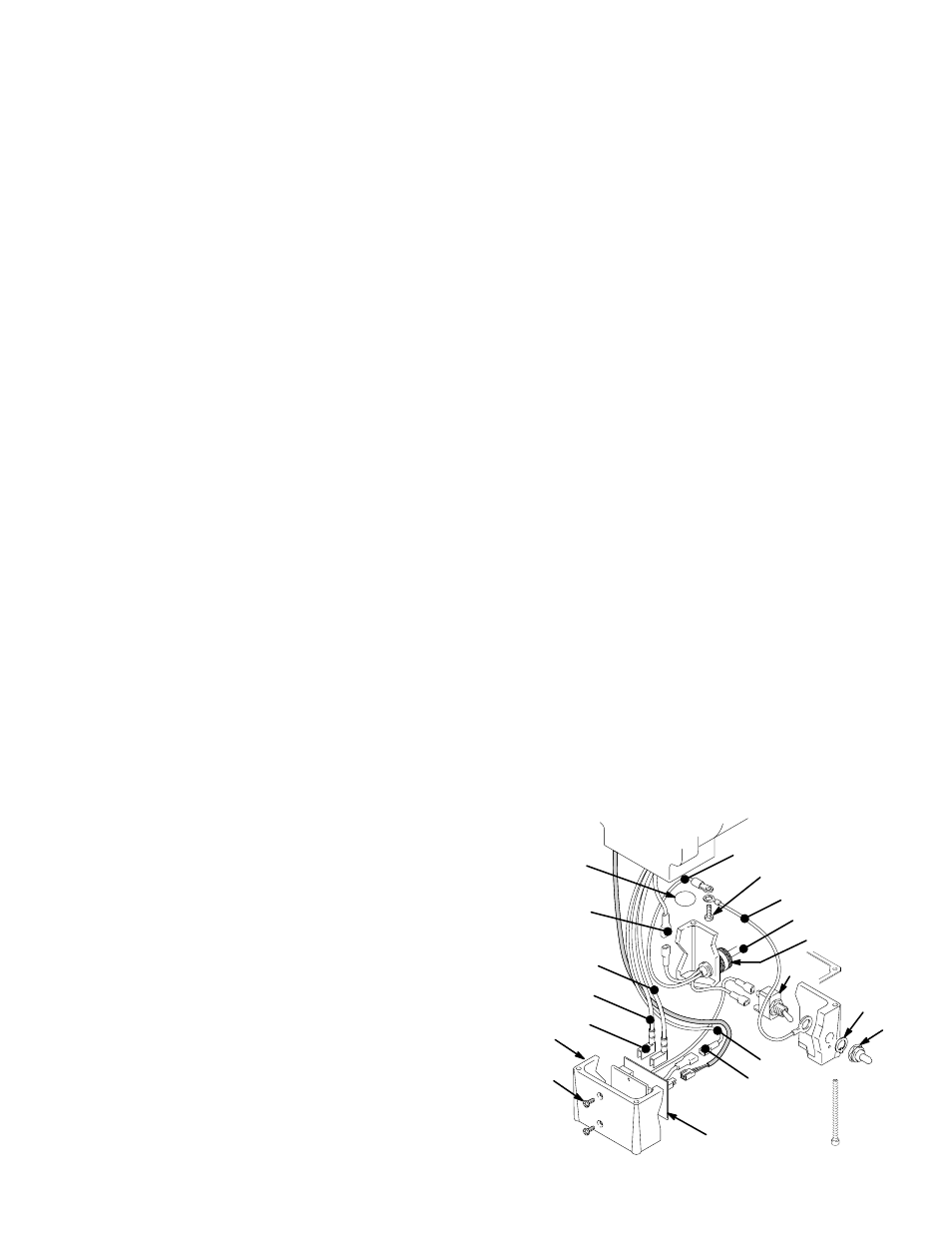
04720
52
47
54
55
53
50
51
49
GREEN
MOTOR
BLACK/
WHITE
BLACK
59
58
RED
4b
GREEN/
YELLOW
4d
4c
48