Frymaster H17 User Manual
Page 81
2-41
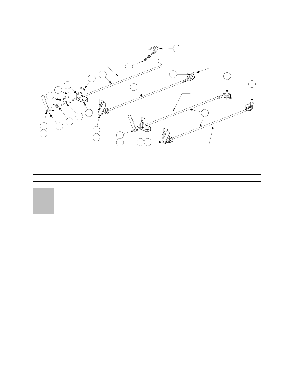
2.12.3 Rear Flush Oil Return Linkage Assemblies and Components
NOTE 3: The "L" and "R" marks on Items 3, 4, and 10 and the
references to right and left in the descriptions of Items 5 and 6
refer to the relative positions of the drain valves to the servicer
when viewed from the rear of the fryer.
806-9803SP
NOTE 2: In assemblies 806-9802SP and 806-6875SP, the "R"
on the cam (Item 10) must face the handle; in 806-9803SP and
806-6874SP, the "L" must face the handle.
NOTE 1: Items 8 through 16 are
used in all four assemblies.
806-6874SP
806-6875SP
4
5
8
9
10
11
12
13
16
15
14
6
3
806-9802SP
3
7
4
1
17
2
17
1
17
17
2
ITEM PART
#
COMPONENT
806-9802SP FootPrint III Dual Vat Left Oil Return Linkage Assembly
806-9803SP FootPrint III Dual Vat Right or Full Vat Oil Return Linkage Assembly
806-6875SP Filter Magic Dual Vat Left Oil Return Linkage Assembly
806-6874SP Filter Magic Dual Vat Right or Full Vat Oil Return Linkage Assembly
1
823-2337
Handle, Oil Return, Left
2
823-2338
Handle, Oil Return, Right
3
901-2772
Handle, Rear Flush Valve, Left
4
902-2772
Handle, Rear Flush Valve, Right
5
810-1764
Rod, FootPrint III Oil Return, Right
6
810-1765
Rod, FootPrint III Oil Return, Left
7
810-1180
Shaft, Filter Magic Oil Return
8 809-0601
Clip,
5
⁄
16
-inch Clevis
9
826-1377
Screw, Set 10-32 x ¼ (Pkg. of 25)
10 810-1186
Cam,
Microswitch
11
826-1366
Nut, 4-40 Hex with External Tooth (Pkg. of 25)
12 807-2103
Microswitch
13 816-0220
Insulation,
Microswitch/Bracket
14
826-1359
Screw, 4-40 x ¾-inch Round Head (Pkg. of 25)
15 900-2571
Bracket,
Microswitch
16
809-0359
Screw, #8 x ¼-inch Slotted Hex Washer Head
17
816-0047
Sleeve, Red Plastic Valve Handle