Frymaster H17 User Manual
Page 12
1-8
9. When replacing the right element (as viewed
from the rear of the fryer), insert pin
terminals into the corresponding pin-holes in
the 6-pin connector. When all pin terminals
have been fully inserted, close the connector
by sliding the halves together until the tabs
snap back into place (reverse procedure in
Step 2).
10. When replacing the left element (as viewed
from the rear of the fryer), use the 9-pin
connector, inserting the leads from the
replacement element and closing the
connector, see previous step.
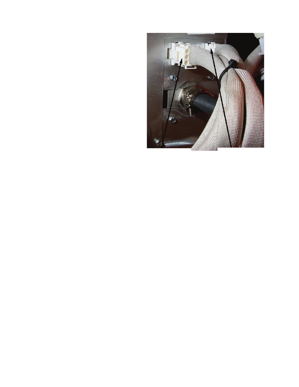
11. Insert the connector(s) into the receptacle(s)
on the rear of the contactor box, ensuring that
the latches lock the connectors in place (see
Step 9).
12. Install the temperature probe wires (marked
for re-assembly) in the corresponding pin
locations.
13. Reconnect the element spring.
14. Place the tilt housing cover over the tilt
housing assembly and secure with screws.
15. Install covers and secure with screws.
16. Position fryer under exhaust hood.
Left Element—
9-Pin Connector
Right Element—
6-Pin
Connector