7 confirming magnetron heater voltage – Furuno FR1500 Mk3 User Manual
Page 55
5-6
5.7 Confirming Magnetron Heater Voltage
Magnetron heater voltage is adjusted at the factory. However, confirm that it is
within the prescribed rating as follows:
1. [MENU] [0] [0] [0] [0] [5] [5] [0] [0] [0] [0] to display the OTHER menu.
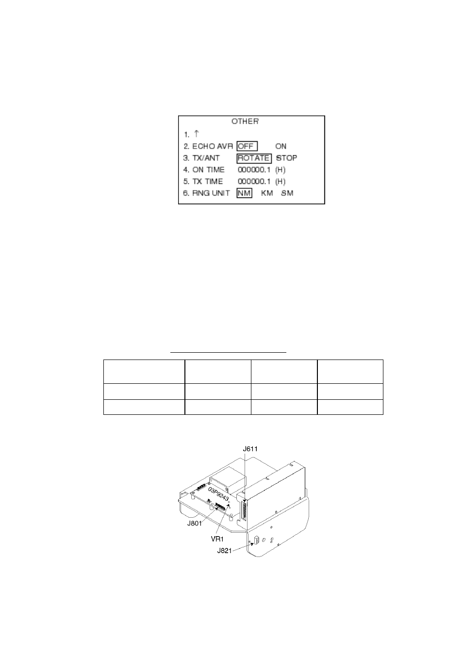
Figure 5-8 OTHER menu
2. Press the [3] key to select STOP from the TX/ANT field and press the [EN-
TER/SELECT] key.
3. Disconnect connector P821 from the scanner unit.
4. Measure on the 0.125 nm and 48 nm range scales, the voltage between pins
#12(+) and #5(-) on connector P801 on the RFC Board (03P9243) in the scan-
ner unit.
5. If the voltage is not within the rating shown in Table 5-2, adjust potentiometer
VR1 on the RFC Board.
Table 5-2 Magnetron ratings
Rating
FR-1505 MK3
(6 kw)
FR-1510 MK3
(12 kW)
FR-1525 MK3
(25 kW)
0.125 nm
7.4 - 7.6 V
7.4 - 7.6 V
8.2 - 8.4 V
48 nm
7.4 - 7.6 V
7.4 - 7.6 V
6.5 - 7.5 V
6. Set ROTATE from the TX/ANT field and press the [ENTER/SELECT] key.
Figure 5-9 RFC Board