3 connection of external buzzer, Table 3-2 output connectors on the spu board, Figure 3-3 connection of external buzzer – Furuno FR1500 Mk3 User Manual
Page 31
3-3
Table 3-2 Output connectors on the SPU Board
Signal Name
Slave display
Buzzer signal
Target signal
(serial data)
Conn. Name
EXT RADAR
EXT ALARM
NAV 1
Conn. No.
J204
J211
J202
Conn. Type
NH, 8 pin
NH, 3 pin
NH, 5 pin
Connectable Equip.
FMD-811, FMD-8010
(Note 1)
OP03-21-3
Speaker w/amp
To GPS, navigator
Remarks
Heading, bearing
video, true trigger
Buzzer drive signal
Signal for speaker
NMEA0183
$ RATLL
$ RARSD
Note 1: Display unit of FR-1505 MARK-3 series, FR-7041, FR-7111 may also be used as
a slave display.
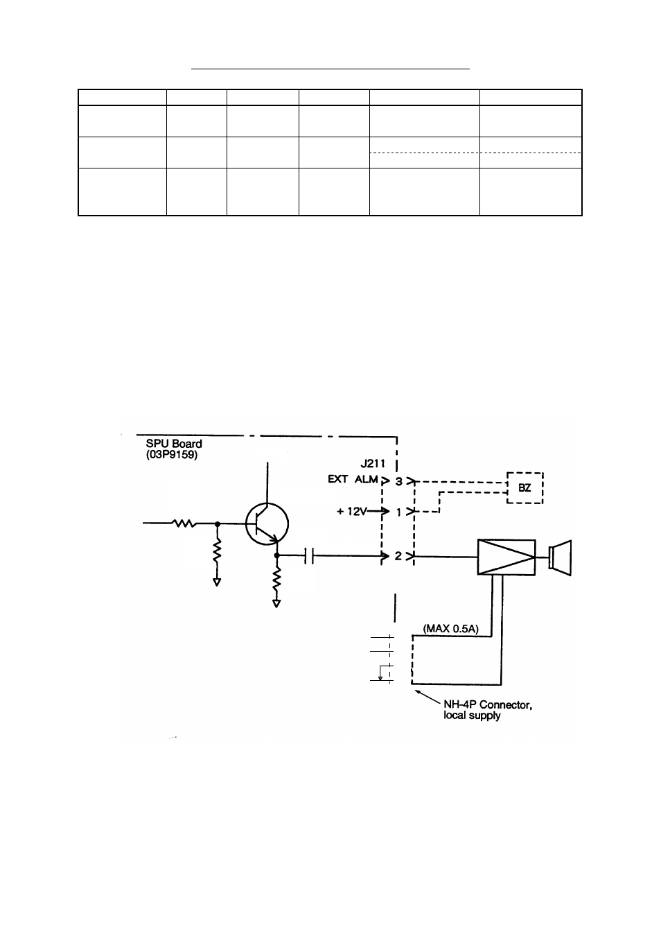
3.3 Connection of External Buzzer
AAn external speaker or buzzer can be connected to this radar via an amplifier
circuit (local supply), as shown in the figure below. Because connector J211 is
used for the internal speaker unplug it and connect the connector from the exter-
nal speaker to J211. Ground the amplifier to nearby connector’s ground terminal.
> 1 >
> 2 >
> 3 >
> 4 >
R232
10K
R422
220
C225
10u
16v
2SC39389R
+12V
+5V
-12V
J212
Piezo-electric buzzer
OP03-21 (option)
Figure 3-3 Connection of external buzzer