Furuno FR1500 Mk3 User Manual
Page 14
1-4
1. Construct a suitable mounting platform referring to the outline drawing at the
back of the manual.
2. Drill four mounting holes of 15 mm diameter and one cable entry hole of about
50 mm diameter in the mounting platform.
3. Lay the rubber mat (supplied) on the mounting platform.
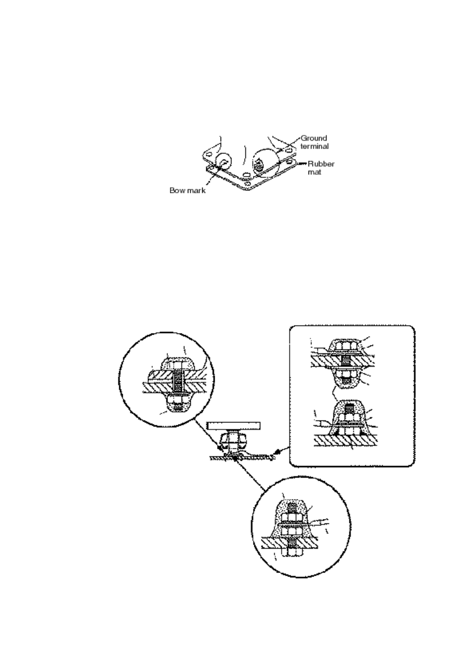
4. Place the scanner unit on the rubber mat orienting the unit so the bow mark on
its base is facing the ship’s bow.
Figure 1-4 Scanner unit, front view
5. Fasten the scanner unit to the mounting platform with M12x60 hex bolts, nuts,
flat washers and seal washers.
6. Using hex bolt (M6x25), nut (M6) and flat washer (M6) establish the ground
system on the mounting platform as shown in Figure 1-5. The location should
be within 370 mm of the ground terminal on the scanner unit. Connect the
ground wire (RW-4747, 370 mm, supplied) between the grounding point and
ground terminal on the scanner unit. Coat the entire ground system with sili-
cone sealant (supplied).
Figure 1-5 How to mount the scanner unit