4 performance monitor pm-30 – Furuno FR-2125V User Manual
Page 56
4-15
4.4 Performance Monitor PM-30
Necessary parts: PM-30 and OP03-150 (Code no. 008-485-490)
Contents of Performance Monitor Kit OP03-150
e
m
a
N
e
p
y
T
y
t
Q
.
o
N
e
d
o
C
d
r
a
o
B
N
I
-
M
P
5
2
2
9
P
3
0
1
0
2
6
-
7
8
4
-
8
0
0
B
w
e
r
c
S
d
a
e
h
-
n
a
P
W
0
0
7
2
C
8
X
3
M
3
4
0
4
-
1
8
8
-
0
0
0
.
y
s
s
A
r
o
t
c
e
n
n
o
C
A
A
-
0
0
3
L
-
P
3
H
V
2
4
1
0
-
1
4
1
-
0
0
0
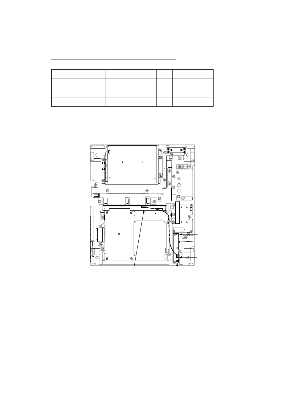
1. Open the monitor and fix it with the stay. See Chapter 1 for instructions.
2. Fasten the PM Board 03P9225 to the location shown below with three screws
(M3X8).
✂
J401
J411
PM Board
03P9225
J402
J403
Figure 4-15 Display unit, inside view
3. Connect J411 to J401 on the PM Board.
4. Connect two connector assemblies (VH3P-L300-AA) to J402 and J403.
5. Solder the other end of the connector assemblies with external cables, one
from ship’s mains and one from the PM-30.
6. Close the monitor.
See also other documents in the category Furuno Sports and recreation:
- FAR-2805 Series (169 pages)
- FR-8062 (2 pages)
- FR-8122 (56 pages)
- CH-37 (90 pages)
- CH-37 (71 pages)
- FAR-2XX7 (4 pages)
- FAR-2XX7 (2 pages)
- FELCOM16 (4 pages)
- FRS-1000B (8 pages)
- FRS1000 (8 pages)
- Ls4100 (48 pages)
- 520 (73 pages)
- Marine Radar (24 pages)
- 1944C-BB (233 pages)
- 1733C (260 pages)
- FR-2105 (197 pages)
- FMD-8010 (50 pages)
- GD-1900C (260 pages)
- Black Box Video Sounder FCV-1200BB (2 pages)
- FR-1505 MARK-3 (4 pages)
- 1762 (252 pages)
- NAVnet DRS12A (44 pages)
- FAR-2127 (136 pages)
- FAR-2137S (8 pages)
- FA30 (6 pages)
- Satellite Compass SC-50/110 (30 pages)
- 1715 (2 pages)
- 1715 (48 pages)
- 1734C (55 pages)
- GD-1720C (53 pages)
- Mu 120c (2 pages)
- NAVNET GD-1920C (239 pages)
- CI-80 (41 pages)
- FAR-28x7 Series (299 pages)
- FAR-2837S (8 pages)
- BBWX1 (2 pages)
- 851 MARK-2 (37 pages)
- 851 MARK-2 (47 pages)
- BBFF3 (1 page)
- CSH-53 (106 pages)
- CSH-53 (108 pages)
- FCV295 (53 pages)
- FR1500 Mk3 (79 pages)
- FI-50 Series (2 pages)
- FCV-1150 (32 pages)