Separate type control head – Furuno FR-2125V User Manual
Page 53
4-12
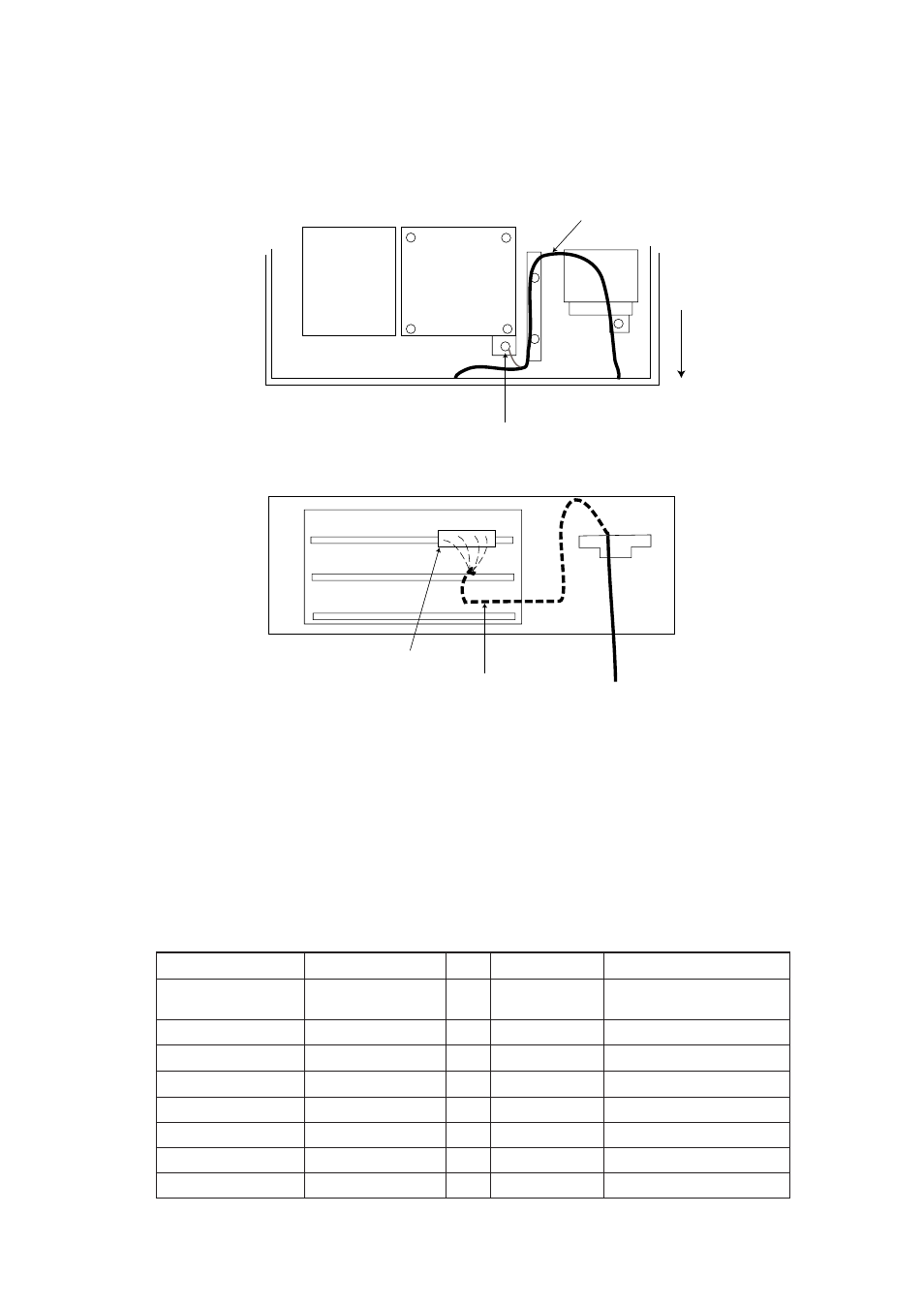
6. Run the connector from the M-card base assy. in front of the GYRO CON-
VERTER Board as in Figure 4-11.
7. Plug the connector from the M-card base assy. in J1 on the RP Board.
8. Fasten the ground wire from the connector at the location shown in Figure 4-
11.
INT Board
GYRO
CONVERTER
Board
FRONT
Fasten ground wire from connector to this screw.
RP connector
(TOP VIEW)
(FRONT VIEW)
RP Board
ARP Board
SPU Board
Route cable between ARP and SPU Boards.
J1
Figure 4-11 Display pedestal, front and top views
9. Fasten the PCB card case cover to the display pedestal.
10.Close the monitor, and then fasten the right arm cover.
Separate type control head
Necessary parts: RP-26-Z-2E (Code no. 008-491-400)
e
m
a
N
e
p
y
T
y
t
Q
.
o
N
e
d
o
C
s
k
r
a
m
e
R
.
y
s
s
A
e
s
a
B
d
r
a
C
-
M
—
1
—
,
.
y
s
s
a
e
l
b
a
C
,
d
r
a
o
B
F
I
.
y
s
s
a
e
s
a
b
d
r
a
c
-
M
d
r
a
o
B
P
R
8
9
2
0
P
4
1
1
0
4
6
-
7
8
4
-
8
0
0
B
w
e
r
c
S
d
a
e
h
-
n
a
P
W
0
0
7
2
C
8
X
4
M
4
5
4
4
-
1
8
8
-
0
0
0
B
w
e
r
c
S
d
a
e
h
-
n
a
P
W
0
0
7
2
C
8
X
3
M
2
4
0
4
-
1
8
8
-
0
0
0
d
e
s
u
t
o
N
A
w
e
r
c
S
d
a
e
h
-
n
a
P
W
0
0
7
2
C
5
X
6
.
2
M
2
3
7
9
-
0
0
8
-
0
0
0
d
e
s
u
t
o
N
A
w
e
r
c
S
d
a
e
h
-
n
a
P
W
0
0
7
2
C
8
X
3
M
1
4
0
1
-
1
8
8
-
0
0
0
d
e
s
u
t
o
N
r
e
h
s
a
w
k
c
o
l
d
e
h
t
e
e
T
W
1
9
1
5
C
4
M
1
6
0
5
-
4
6
8
-
0
0
0
r
e
h
s
a
w
k
c
o
l
d
e
h
t
e
e
T
W
1
9
1
5
C
3
M
1
4
0
5
-
4
6
8
-
0
0
0
d
e
s
u
t
o
N