Separating the control head, Display unit modification procedure – Furuno FR-2125V User Manual
Page 16
1-9
Separating the control head
The control head connects to the display unit with a connection cable, thus it can
be located where desired, using the separate control head kit (option).
Separate type control head kit (Type: OP03-157, Code No.: 008-500-630)
e
m
a
N
e
p
y
T
y
t
Q
.
o
N
e
d
o
C
s
k
r
a
m
e
R
.
y
s
s
A
e
l
b
a
C
P
1
/
P
0
2
B
S
4
6
4
2
L
U
1
2
1
8
-
0
4
1
-
0
0
0
2
2
4
9
S
3
0
,
m
0
1
t
e
e
F
r
e
b
b
u
R
p
il
s
n
o
N
3
0
0
5
-
J
S
4
7
8
7
-
1
0
8
-
0
0
0
e
p
a
t
d
e
d
i
s
-
e
l
b
u
o
d
h
t
i
W
)
V
(
r
e
v
o
C
t
n
o
r
F
r
o
t
i
n
o
M
1
3
7
1
-
4
4
1
-
3
0
1
0
6
5
-
4
7
2
-
0
0
1
e
t
a
l
P
g
n
i
x
i
F
B
K
1
9
6
1
-
4
4
1
-
3
0
1
0
4
9
-
3
6
2
-
0
0
1
)
V
(
e
t
a
l
P
e
l
d
n
a
H
2
3
7
1
-
4
4
1
-
3
0
1
0
7
5
-
4
7
2
-
0
0
1
e
l
d
n
a
h
g
n
i
x
i
f
r
o
F
B
K
r
e
v
o
C
t
s
u
D
3
9
6
1
-
4
4
1
-
3
0
1
0
6
7
-
1
7
2
-
0
0
1
w
e
r
c
S
t
e
s
p
U
4
0
3
S
U
S
0
1
X
5
M
2
8
8
2
-
2
0
8
-
0
0
0
w
e
r
c
S
g
n
i
d
n
i
B
0
0
7
2
C
8
X
4
M
2
7
0
4
-
6
0
8
-
0
0
0
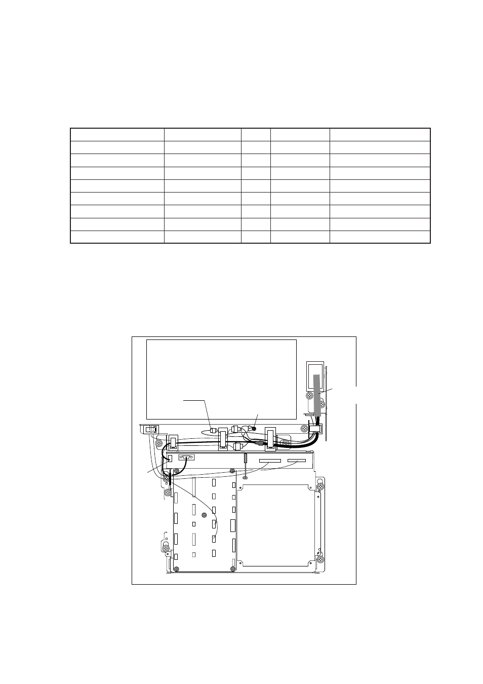
Display unit modification procedure
1. Raise the monitor unit and fix it with the stay. Refer to procedure for tabletop
mounting on page 1-5.
2. Inside the display pedestal, unplug two connectors from the control head cable
(P412 from MOTHER Board and J583) and unfasten two earth wires.
MB 03P9251
INT
03P9252
J583
P412
J418
Earth Wire
PTU COVER
Control Head
Cable
Figure 1-12 Display unit, inside view