Installation of optional equipment, 1 gyro converter gc-8 – Furuno FR-2125V User Manual
Page 42
4-1
INSTALLATION OF OPTIONAL EQUIPMENT
4.1 Gyro Converter GC-8
The Gyro Converter GC-8, incorporated inside the radar display unit, converts
analog gyrocompass reading into digital coded bearing data for display on the
radar display.
This section explains how to install and the GC-8 (mainly consisting of the GYRO
CONVERTER Board) and set it up according to the gyrocompass connected.
Installation and connection of the GYRO
CONVERTER Board
Necessary Parts: GC-8 (Code No. 008-446-520)
e
m
a
N
e
p
y
T
y
t
Q
.
o
N
e
d
o
C
d
r
a
o
B
r
e
t
r
e
v
n
o
C
o
r
y
G
6
0
1
1
P
4
6
1
0
2
2
-
2
1
4
-
4
0
0
s
w
e
r
c
S
W
0
0
7
2
C
,
8
X
3
M
5
4
0
4
-
1
8
8
-
0
0
0
r
e
k
c
i
t
S
1
1
2
0
2
-
4
1
0
-
4
6
1
1
0
7
-
2
3
1
-
0
0
1
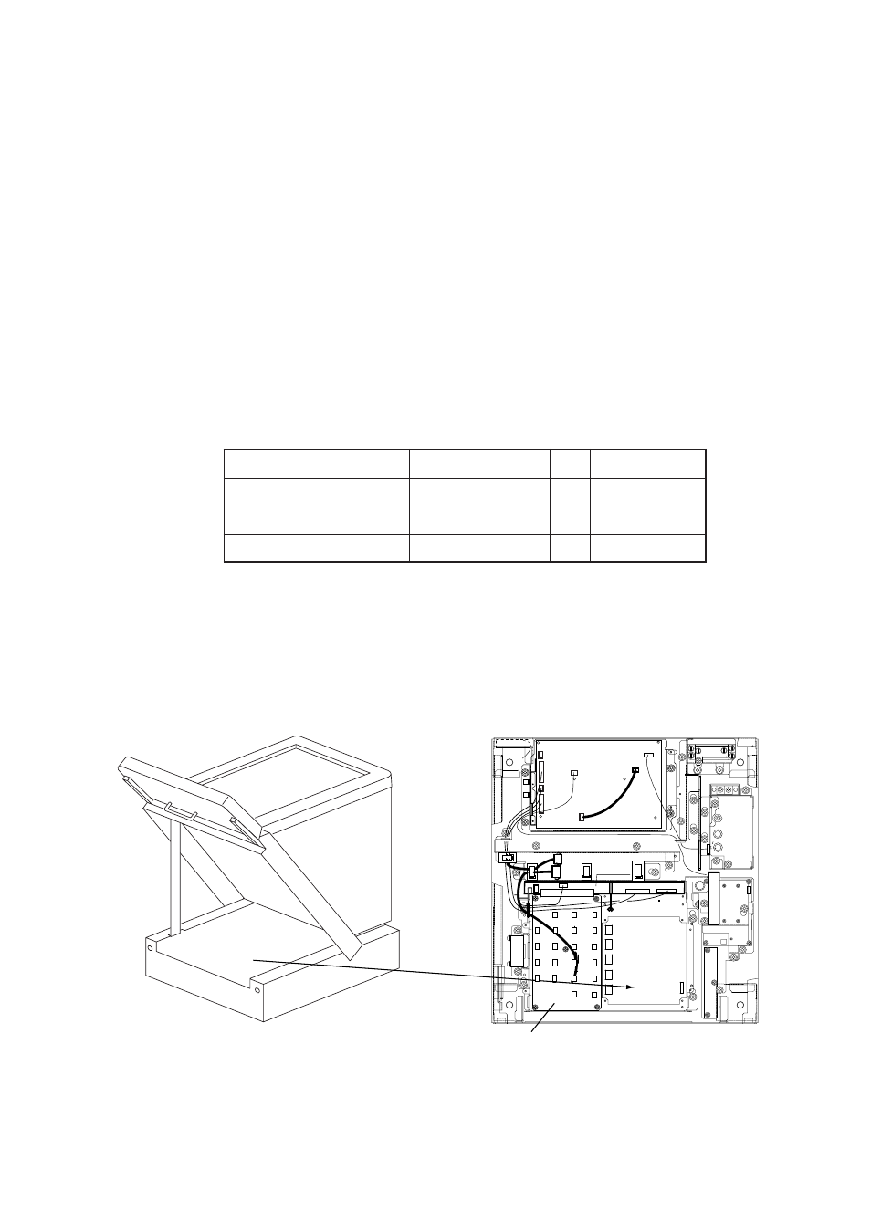
1. Turn off the main POWER switch.
2. Open the monitor and fix it with the stay. (See Chapter 1 for instructions.) Turn
off the internal power switch if so equipped. Unfasten four screws to remove
the shield cover for the INT Board.
3. Fasten the GYRO CONVERTER Board inside the display unit with four washer-
head screws (supplied).
PTU BOARD
03P9245A(-F)
MB BOARD
03P9251
INT BOARD
03P9252
GYRO
CONVERTER
BOARD
64P1106
Figure 4-1 Display unit, inside view