Furuno FR-2125V User Manual
Page 18
1-11
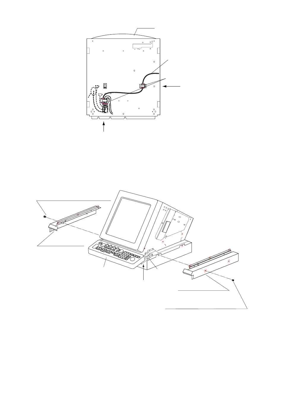
Monitor
J582
J581
Control Head Cable
Clamp
Remove clamp
from left side
Remove clamp from rear side
Figure 1-14 Clamp position
11. Unfasten four upset screws (
6
) at the bottom of the right and left KB arms to
dismount the control head.
12.Unfasten three screws (M4X10) and two screws (M4X8) to remove the right
lower cover (
7
) and the left lower cover (
8
).
Right Lower Cover (
7
)
Pan-head Screw (M4X10, 3 pcs., upper)
Binding Screw (M4X8, 2 pcs., lower)
Pan-head Screw (M4X10, 3 pcs., upper)
Binding Screw (M4X8, 2 pcs., lower)
Left Lower Cover (
8
)
Right KB Arm
Upset Screw (
6
)
(M5X25, 4 pcs.,
including those on
opposite side)
Control Head
Figure 1-15 Display unit, front view
See also other documents in the category Furuno Sports and recreation:
- FAR-2805 Series (169 pages)
- FR-8062 (2 pages)
- FR-8122 (56 pages)
- CH-37 (90 pages)
- CH-37 (71 pages)
- FAR-2XX7 (4 pages)
- FAR-2XX7 (2 pages)
- FELCOM16 (4 pages)
- FRS-1000B (8 pages)
- FRS1000 (8 pages)
- Ls4100 (48 pages)
- 520 (73 pages)
- Marine Radar (24 pages)
- 1944C-BB (233 pages)
- 1733C (260 pages)
- FR-2105 (197 pages)
- FMD-8010 (50 pages)
- GD-1900C (260 pages)
- Black Box Video Sounder FCV-1200BB (2 pages)
- FR-1505 MARK-3 (4 pages)
- 1762 (252 pages)
- NAVnet DRS12A (44 pages)
- FAR-2137S (8 pages)
- FAR-2127 (136 pages)
- FA30 (6 pages)
- Satellite Compass SC-50/110 (30 pages)
- 1715 (2 pages)
- 1715 (48 pages)
- 1734C (55 pages)
- GD-1720C (53 pages)
- Mu 120c (2 pages)
- NAVNET GD-1920C (239 pages)
- CI-80 (41 pages)
- FAR-28x7 Series (299 pages)
- FAR-2837S (8 pages)
- BBWX1 (2 pages)
- 851 MARK-2 (47 pages)
- 851 MARK-2 (37 pages)
- BBFF3 (1 page)
- CSH-53 (106 pages)
- CSH-53 (108 pages)
- FCV295 (53 pages)
- FR1500 Mk3 (79 pages)
- FI-50 Series (2 pages)
- FCV-1150 (32 pages)