19 interference rejector – Furuno FAR-2107 User Manual
Page 56
1. RADAR OPERATION
1-30
1.19 Interference
Rejector
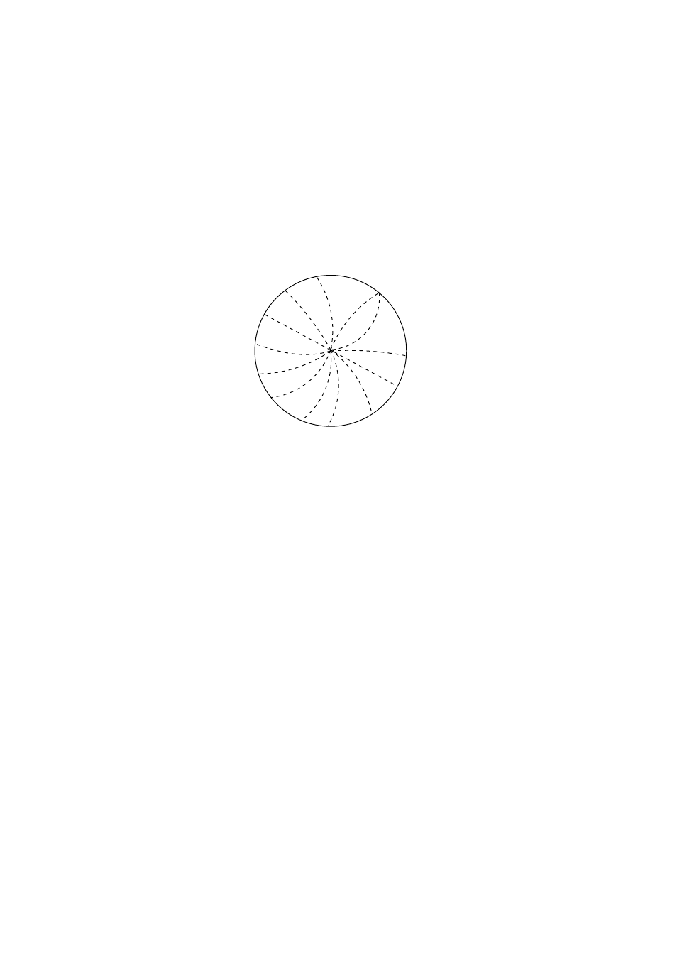
Mutual radar interference may occur in the vicinity of another shipborne radar
operating in the same frequency band. It is seen on the screen as a number of
bright spikes either in irregular patterns or in the form of usually curved
spoke-like dotted lines extending from the center to the edge of the picture.
Activating the interference rejector circuit can reduce this type of interference.
The interference rejector is a kind of signal correlation circuit. It compares the
received signals over successive transmissions and suppresses randomly
occurring signals. There are three levels of interference rejection depending on
the number of transmissions that are correlated.
Interference
1. Roll the trackball to choose the IR indication at the left side of the screen.
2. Push the left button successively to choose rejection level desired and then
push the wheel or the left button. “3” provides the highest degree of
suppression.
Note: The interference rejector can also be adjusted from the PICTURE box.