System configuration – Furuno FAR-2107 User Manual
Page 19
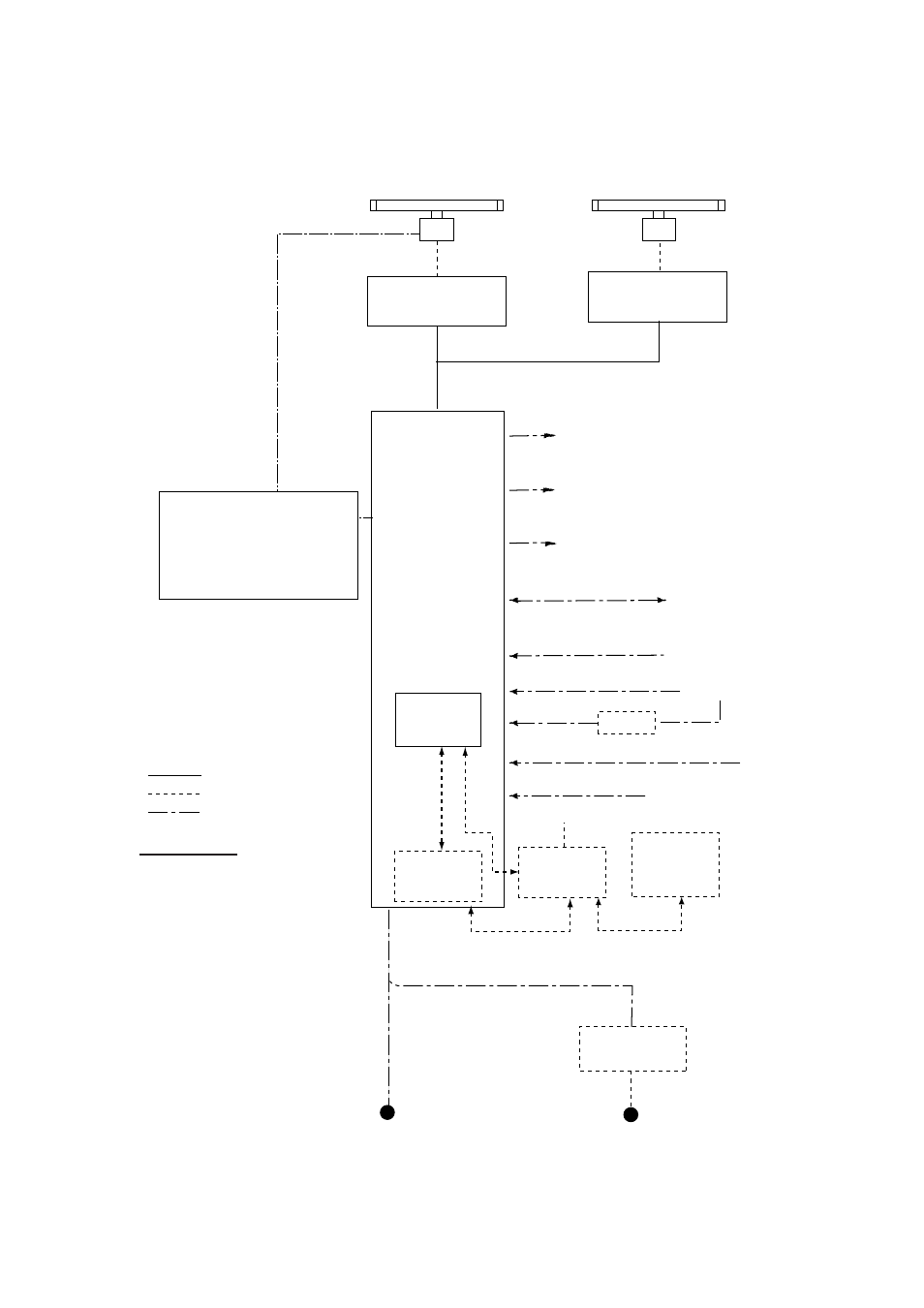
SYSTEM CONFIGURATION
xvii
Console type RCN-001/RCN-002
ANTENNA UNIT
(Performance Monitor PM-51 built in)
TRANSCEIVER UNIT
RTR-082
For FAR-2837SW
(-D)
FAR-2137S(-D)/2837S(-D)/2837SW(-D)
POWER SUPPLY UNIT
PSU-007
For FAR-2137S
(-D)
/2837S
(-D)
OR
POWER SUPPLY UNIT
PSU-011*
(For FAR-2827W
(-D)
/2837SW
(-D)
CONSOLE
RCN-001/002
FAR-2117(-D)/2127(-D)/
2817(-D)/2827(-D)/2827W(-D)
Waveguide or
Coax cable
(For FAR-2837SW
(-D)
)
AIS
Gyrocompass
AD-100
TRANSCEIVER UNIT
RTR-081
For FAR-2827W(-D)
Waveguide
(For FAR-2827W
(-D)
)
: Option
: Dockyard supply
: Standard
Category of Units
Antenna unit:
Exposed to weather
All other units: Protected from weather
ANTENNA UNIT
(Performance Monitor PM-31 built in)
100-115 VAC/
220-230 VAC
1
φ
, 50/60 Hz
Transformer Unit
RU-1803
440 VAC
1
φ
, 50/60 Hz
AC spec
Alarm
VDR
External Monitor
Navigator (INS, GPS, etc.)
IEC-61162-1 Serial Data
(Input/Output)
IEC-61162-1 Serial Data
(Input)
Speed Log
Track Control Unit
Memory Card
Interface Unit
CU-200
Switching Hub
HUB-100
100-230 VAC
PROCESSOR
UNIT
RPU-013
May also
be installed
externally.
OR
Memory Card
Interface Unit
CU-200
(Max. 2 total)
* Russian flag only