Adept EX SmartContoller User Manual
Page 36
Chapter 3: Operation
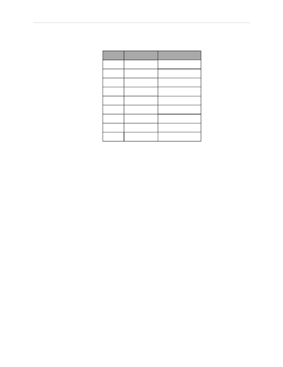
Table 3-5. RS-422/485 Connector Pin Assignments
Pin
Signal
Type
1
NC
2
RXD+
Input
3
TXD+
Output
4
TXD-
Output
5
GND
Ground
6
RXD–
Input
7
NC
8
EXPIO_5V
Output
9
GND
Ground
To change the configuration of the RS-422/485 port, see Configuring Serial Ports on page 33.
See the previous table for the eV+ designation when referenced in the eV+ ATTACH or FSET
instructions.
3.5 Connecting User-Supplied Safety and Power-Control Equipment
The user-supplied safety and power-control equipment connects to the system through the
XUSR and XFP connectors on the controller. The XUSR connector (25-pin) and XFP (15-pin)
connector are both female D-sub connectors located on the front panel of the controller. Refer to
the following table for the XUSR pin-out descriptions. Refer to the table Contacts Provided by
the XFP Connector on page 37 for the XFP pin-out descriptions. See the figure CAT-3 E-Stop Cir-
cuit on XUSR and XFP Connectors on page 40 for the XUSR wiring diagram.
Adept SmartController EX User’s Guide, Rev. B
Page 36 of 96