AltiGen MAXCS 7.0 Telephony Hardware User Manual
Page 41
AltiGen Triton/Proton Telephony Boards
Telephony Hardware Manual 35
•
On-Board telephony power supply:
–
Input 12Vdc from power connector
–
Output -24Vdc (talking battery) and 90Vac (ring voltage)
Note:
When the board is configured to use an audio input port, the first port cannot be
used for an extension.
Note:
This board complies with Section 508 of the Rehabilitation Act of 1973. This
includes compatibility with hearing aids, cochlear implants, assistive listening
devices, and TTYs.
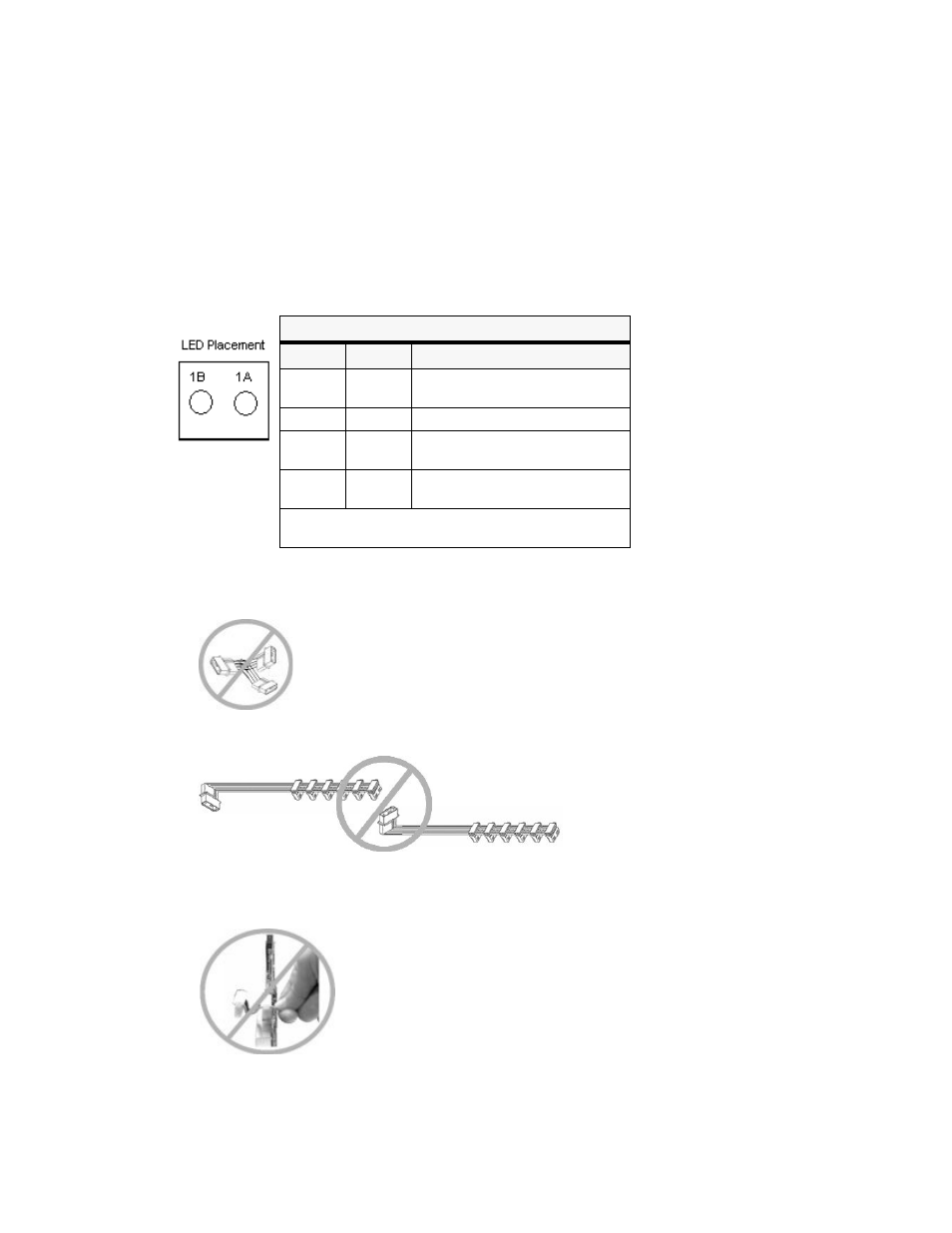
LED Status
LED Indicators
LED 1B LED 1A Status
ON
ON
5V is OK; 12V is OK – normal
operation
OFF
OFF
Power cable not plugged in
ON
OFF
5V less than 4.5V but more than
3V – bad PC 5V power
OFF
ON
12V less than 9V – bad PC 12V
power
LED 2, located near the 12V connector, is a red LED
for diagnostic purposes. If it is ON, the fuse is blown.
Warning:
•
Do not use a "Y" splitter to connect two sets of power cables.
•
Do not chain two sets of power cable together from a single power connector.
•
Do not pull the cable when unplugging the power connector. This may damage the
cable assembly. If it is too difficult to remove the plug from the power connector,
please use pliers to remove the plug.