3 12v power connector, 4 optional terminal block, Figure 5-2: dvi-d connector – IEI Integration LCD-KIT Series v3.00 User Manual
Page 35: Figure 5-3: 12v power connector, Table 5-3: dvi-d connector pinouts
LCD-KIT
P a g e 26
Pin
Description
Pin
Description
Pin
Description
1
TMDS Data2-
9
TMDS Data1-
17
TMDS Data0-
2
TMDS Data2+
10
TMDS Data1+
18
TMDSData0+
3
TMDS Data2/4 Shield
11
TMDS Data1/3 Shield
19
TMDS Data0/5 Shield
4
TMDS Data4-
12
TMDS Data3-
20
TMDS Data5-
5
TMDS Data4+
13
TMDS Data3+
21
TMDS Data5+
6
DDC Clock [SCL]
14
+5 V Power
22
TMDS Clock Shield
7
DDC Data [SDA]
15
Ground (for +5 V)
23
TMDS Clock +
8
Analog vertical sync
16
Hot Plug Detect
24
TMDS Clock -
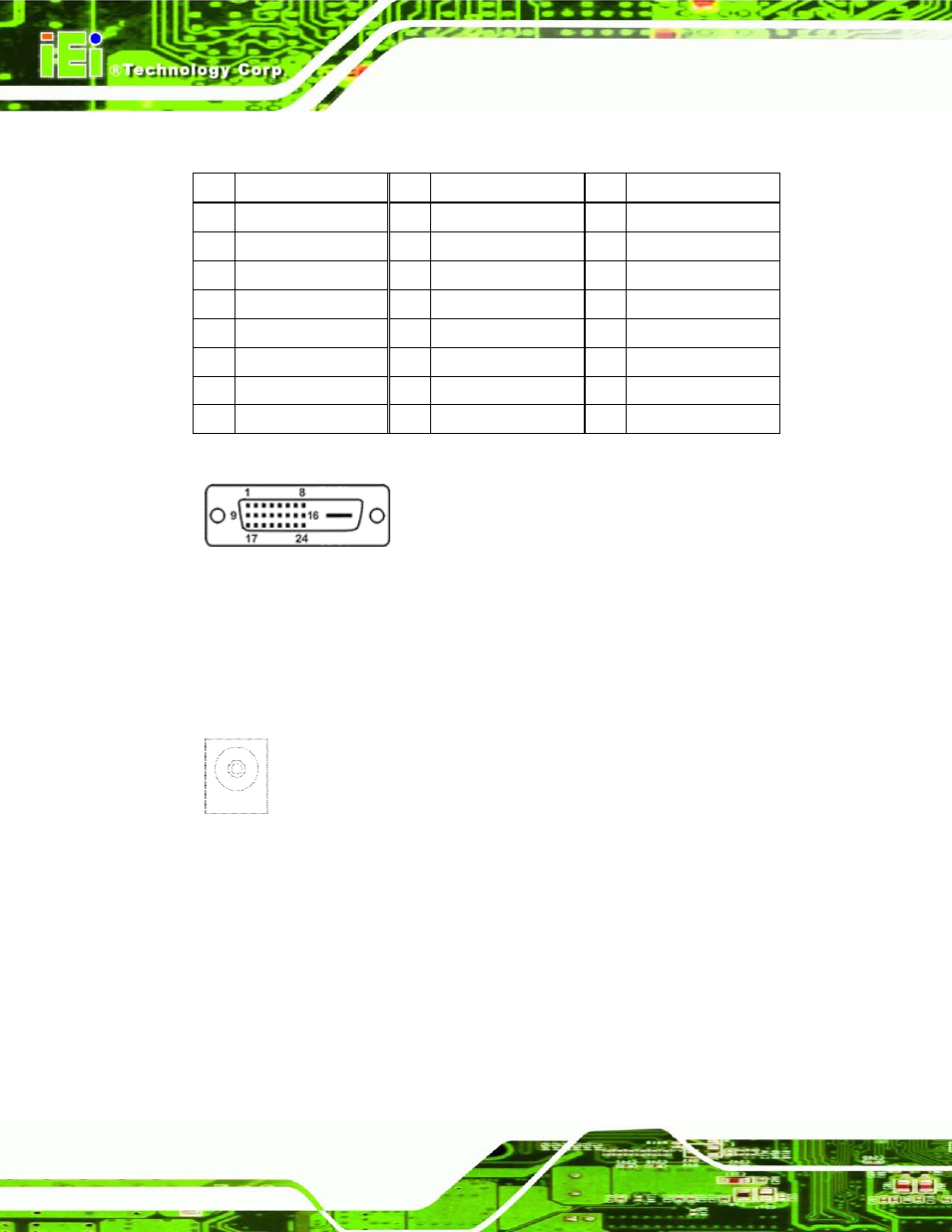
Table 5-3: DVI-D Connector Pinouts
Figure 5-2: DVI-D Connector
5.4.3 12V P o we r Co n n e c to r
Use the rear panel +12V DC (or 9~36V DC on M models) jack to connect the monitor to a
power source.
Figure 5-3: 12V Power Connector
5.4.4 Op tio n a l Te rm in a l Blo c k
Use the rear panel 3-pin terminal block DC power connector to connect the monitor to a
DC power source.