3 connectors, Figure 1-3: typical lcd-kit rear view, Figure 1-4: typical lcd-kit connectors – IEI Integration LCD-KIT Series v3.00 User Manual
Page 14
LCD-KIT
P a g e 5
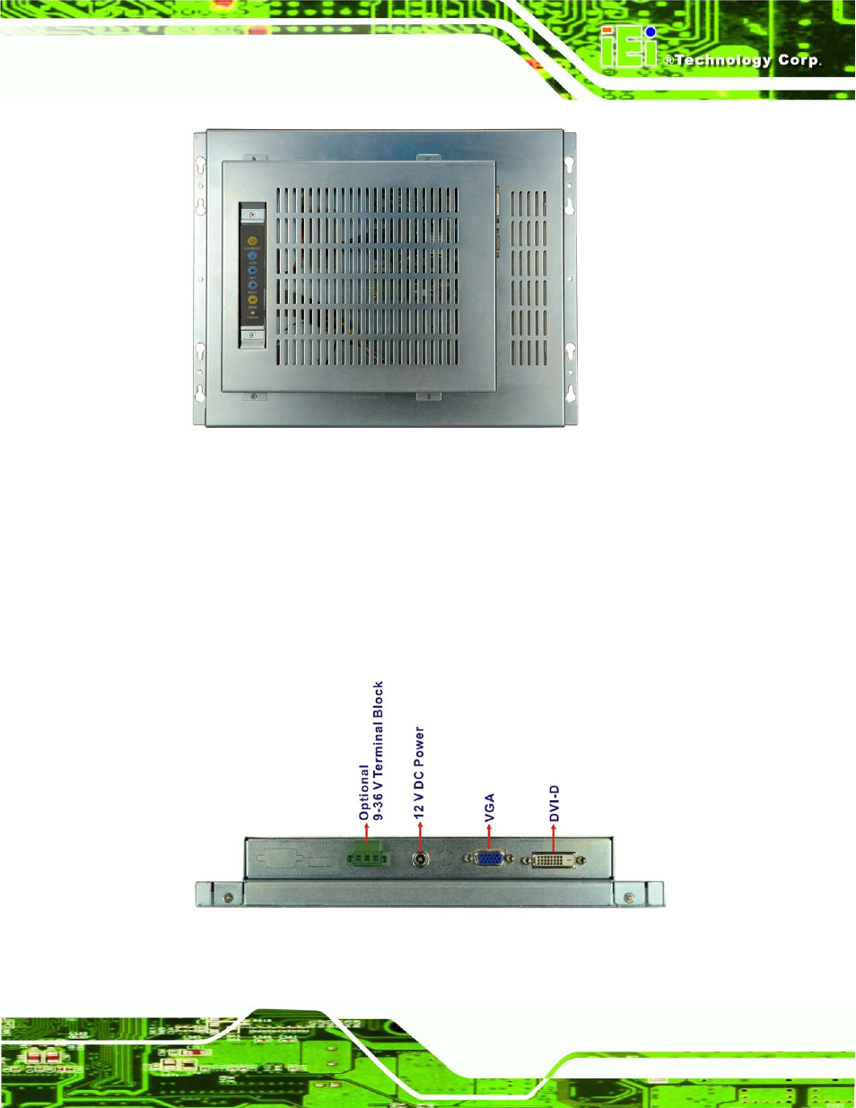
Figure 1-3: Typical LCD-KIT Rear View
1.5.3 Co n n e c to rs
Each LCD-KIT series LCD monitor has a number of interface connectors on either the top
or right panel of the chassis (when viewing the rear panel). Figure 1-4 shows a typical
LCD-KIT connector panel. Each model may include or exclude additional connectors.
Refer to Section 2.3 for listings of LCD-KITs and their connectors. All connectors are fully
described in Section 5.4.
Figure 1-4: Typical LCD-KIT Connectors