3 rj-45 to db-9 serial cable connection, 4 usb device connection, Figure 3-31: serial device connector – IEI Integration AFL-ххA-N26 User Manual
Page 60
AFL-xxA-N26 Series Panel PC
Page 60
3.10.3 RJ-45 to DB-9 Serial Cable Connection
The AFL-xxA-N26 has one serial device connector on the bottom panel. The serial device
slots (RJ-45) connect to a cable with a standard DB-9 connector at the other end. Follow
the steps below to connect a serial device to the AFL-xxA-N26 panel PC.
Step 1:
Locate the RJ-45 connector
. The location of the RJ-45 serial port connector is
shown in Chapter 1. The RJ-45 connector for the serial ports can be identified
easily as the RJ-45 for the network has two LEDs on the port, while the
connector for the serial cable don’t.
Step 2:
Insert the RJ-45 to DB-9 cable.
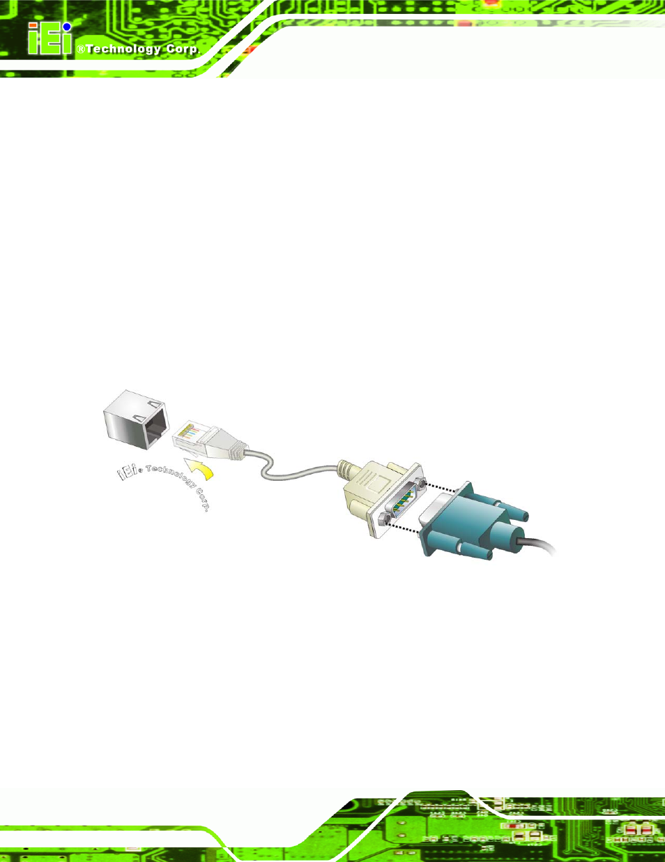
Step 3:
Insert the serial connector
.
Insert the DB-9 connector of a serial device into
the DB-9 connector on the cable. See Figure 3-30.
Figure 3-31: Serial Device Connector
Step 4:
Secure the connector
. Secure the serial device connector to the external
interface by tightening the two retention screws on either side of the connector.
Step 0:
3.10.4 USB Device Connection
There are two external USB 2.0 connectors. To connect a USB 2.0 or USB 1.1 device,
please follow the instructions below.