11 lvds backlight connector (inverter1), 12 mcu connector (jp8), 13 mcu connector (hotkey_cn1) – IEI Integration AFL-ххA-N26 User Manual
Page 125: Table 7-13: mcu connector (jp8) pinouts, Table 7-14: mcu connector (hotkey_cn1) pinouts
AFL-xxA-N26 Series Panel PC
Page 125
7.2.11 LVDS Backlight Connector (INVERTER1)
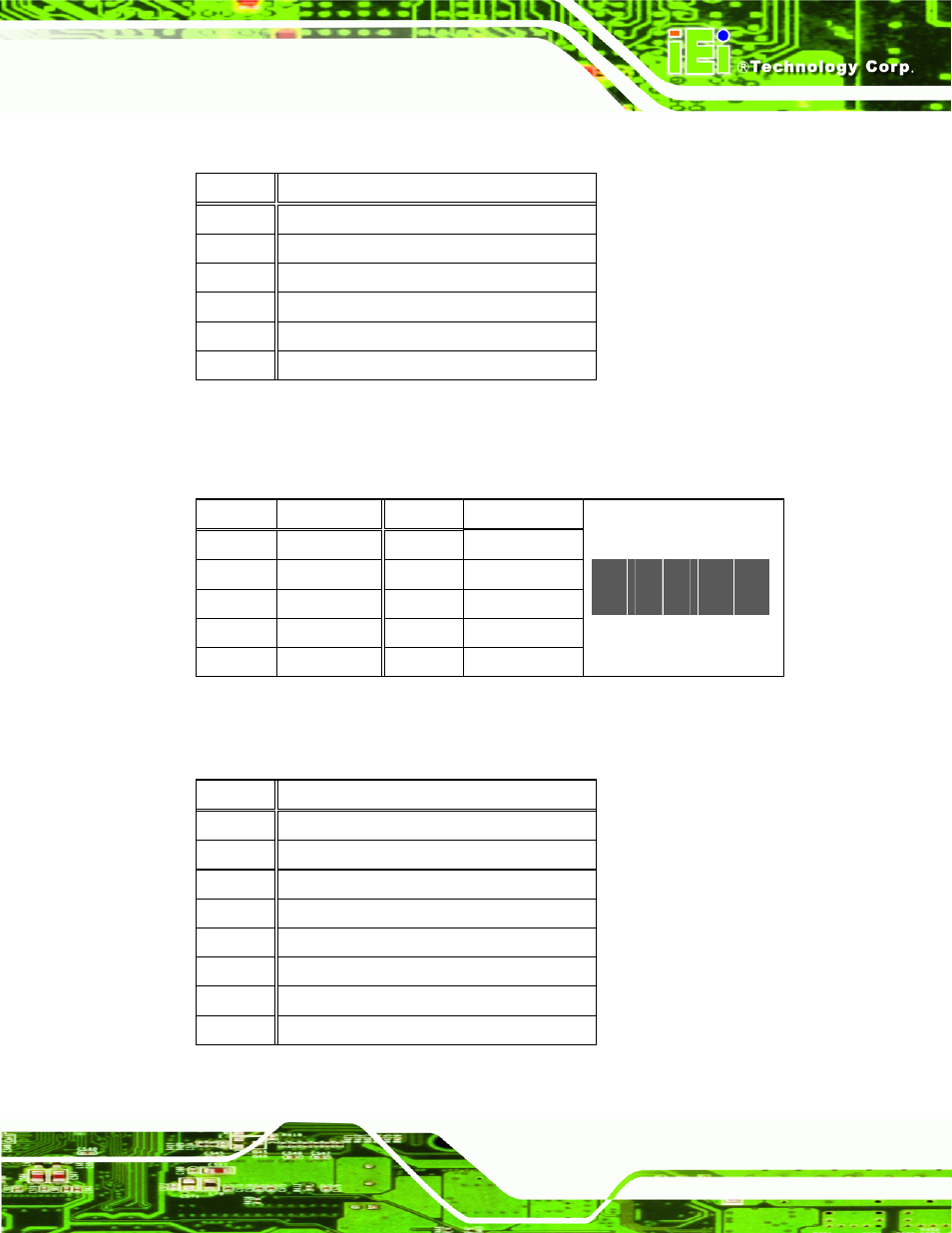
7.2.12 MCU Connector (JP8)
PIN NO.
DESCRIPTION PIN NO.
DESCRIPTION
1 MCLR 2 +5V
3 +5V 4 MCU_IR
5 ICSPCLK
6 AUTO_CLK
7 ICSPDAT
8 AUTO_DATA
9 GND 10
GND
2
10
y
y
y
y
y
y
y
y
y
y
1
9
Table 7-13: MCU Connector (JP8) Pinouts
7.2.13 MCU Connector (HOTKEY_CN1)
PIN NO.
DESCRIPTION
1 +12V
2 +12V
3 BLON
4 BRIGHTNESS
5 GND
6 GND
Table 7-12: LVDS Backlight Connector (INVERTER1) Pinouts
PIN NO.
DESCRIPTION
1 AUTO_DIMMING
2 LOCK_BUTTON
3 VOL+
4 VOL-
5 BRIGHT+
6 BRIGHT-
7 LCD_ON_OFF
8 GND
Table 7-14: MCU Connector (HOTKEY_CN1) Pinouts
This manual is related to the following products: