7 at/atx mode selection, 1 at power mode, At/atx – IEI Integration AFL-ххA-N26 User Manual
Page 41: Election, Figure 3-12: at/atx switch location
AFL-xxA-N26 Series Panel PC
Page 41
WARNING:
Over-tightening back cover screws will crack the plastic frame.
Maximum torque for cover screws is 5 kg-cm (0.36 lb-ft/0.49 Nm).
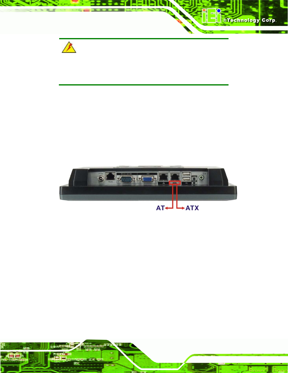
3.7 AT/ATX Mode Selection
AT and ATX power modes can both be used on the AFL-xxA-N26 series. The selection is
made through an AT/ATX switch on the bottom panel (Figure 3-12). To select AT mode or
ATX mode, follow the steps below.
Step 1:
Locate the AT/ATX switch on the bottom panel (Figure 3-12).
Figure 3-12: AT/ATX Switch Location
Step 2:
Adjust the AT/ATX switch.
Step 0:
3.7.1 AT Power Mode
With the AT mode selected, the power is controlled by a central power unit rather than a
power switch. The AFL-xxA-N26 panel PC turns on automatically when the power is
connected. The AT mode benefits a production line to control multiple panel PCs from a
central management center and other applications including:
ATM
Self-service
kiosk
Plant environment monitoring system
Factory automation platform