2 serial device connection (db-9), Figure 3-29: lan connection – IEI Integration AFL-ххA-N26 User Manual
Page 58
AFL-xxA-N26 Series Panel PC
Page 58
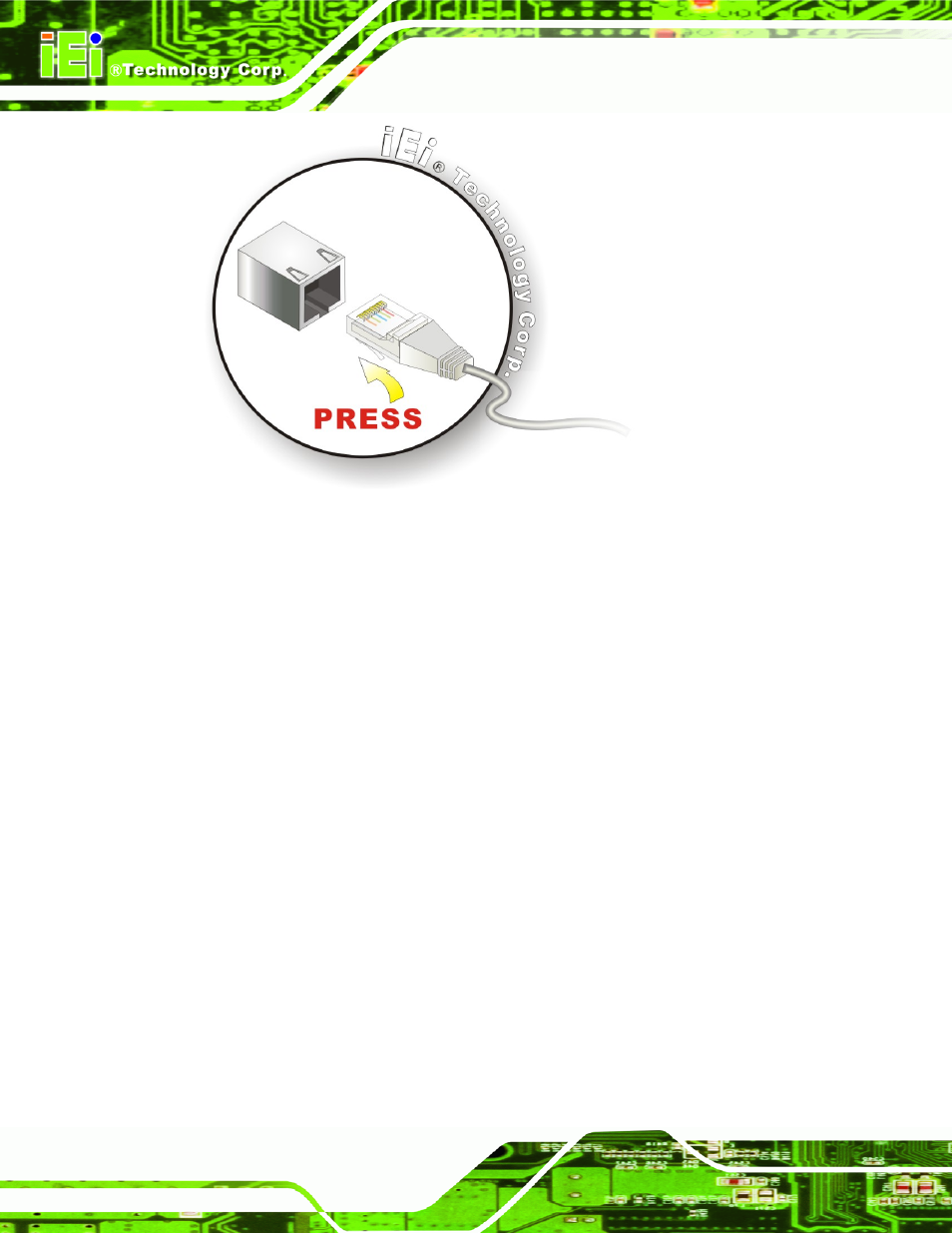
Figure 3-29: LAN Connection
Step 3:
Insert the LAN cable RJ-45 connector.
Once aligned, gently insert the LAN
cable RJ-45 connector into the onboard RJ-45 connector.
Step 0:
3.10.2 Serial Device Connection (DB-9)
The AFOLUX AFL-xxA-N26 Series has one male DB-9 connector on the bottom panel for
serial devices to be connected. Follow the steps below to connect a serial device to the
AFOLUX AFL-xxA-N26 Series panel PC.
Step 1:
Locate the DB-9 connector
. The location of the DB-9 connector is shown in
Chapter 1
.
Step 2:
Insert the serial connector
. Insert the DB-9 connector of a serial device into
the DB-9 connector on the bottom panel. See Figure 3-30.
This manual is related to the following products: