Figure 3-6: pcie mini slot location, Figure 3-7: pcie mini card installation – IEI Integration AFL-ххA-N26 User Manual
Page 37
AFL-xxA-N26 Series Panel PC
Page 37
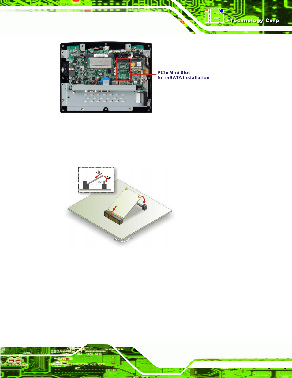
Figure 3-6: PCIe Mini Slot Location
Step 3:
Insert into the socket at an angle
. Line up the notch on the card with the notch
on the connector. Slide the PCIe Mini card into the socket at an angle of about
20º.
Figure 3-7: PCIe Mini Card Installation
Step 4:
Push down until the card clips into place
. Push the other end of the card
down until it clips into place on the plastic connector.
Step 5:
Attach the thermal pad onto the mSATA card
. Use the thermal pad come with
the AFL-xxA-N26 to attach onto the controller chips of the mSATA card
(Figure 3-8). If there is a label sticker on the mSATA card, remove the sticker
first.
This manual is related to the following products: