4 audio connectors, 5 can-bus terminal block, 6 hdmi connector – IEI Integration UPC-V315-QM77 User Manual
Page 44: Figure 3-20: at/atx power mode switch, Figure 3-21: can-bus terminal block pinouts
UP C-V315-QM77 P a n e l P C
P a g e 33
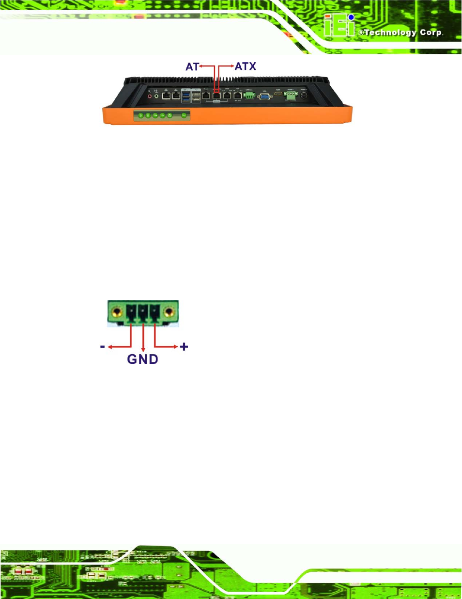
Figure 3-20: AT/ATX Power Mode Switch
3.7.4 Au d io Co n n e c to rs
The audio jacks connect to external audio devices.
Microphone (Pink): Connects a microphone.
Line Out port (Green): Connects to a headphone or a speaker. With
multi-channel configurations, this port can also connect to front speakers.
3.7.5 CAN-b u s Te rm in a l Blo c k
There is one 3-pin CAN-bus terminal block. The pinouts are shown in Figure 3-21
Figure 3-21: CAN-bus Terminal Block Pinouts
3.7.6 HDMI Co n n e c to r
The HDMI connector transmits a digital signal to compatible HDMI display devices such
as a TV or computer screen. To connect the HDMI cable to the UPC-V315-QM77, follow
the steps below.
S te p 1:
Locate the HDMI connector. The location is shown in Chapter 1.
S te p 2:
Align the connector. Align the HDMI connector with the HDMI port. Make sure
the orientation of the connector is correct.